Electrically Insulated Screen and Method of Erecting an Electrically Insulated Screen

a technology of electrical insulation and electrical insulation, applied in the field of sensor devices, can solve the problems of limited useful surface of the sensor device, reduced gripping stability, limited application range, etc., and achieve the effect of increasing the gripping stability

Active Publication Date: 2014-11-06
ONROBOT HUNGARY KFT
View PDF7 Cites 27 Cited by
  • Summary
  • Abstract
  • Description
  • Claims
  • Application Information

AI Technical Summary

Benefits of technology

[0005]In the case of pressure sensor devices having elastic surface, as a result of applying a gripping force, the surface of the sensor device fits to the surface of the object, thereby increases the stability of the grip and information about the surface and material characteristics of the object can be collected from larger surface. In many prior art solutions, it was attempted to cover rigid structure sensor devices with a flexible material.

Problems solved by technology

It is a great disadvantage of the point-like contact that little information can be obtained about the given object and its surface, and stability of gripping is also reduced.
It is a disadvantage of this approach that the useful surface of the sensor device, on which it can detect with an appropriate accuracy the components of forces acting thereon, is limited by the emission angle of the light emitting element and by the angle of vision of the light detecting elements.
A further disadvantage of the approach is that as a result of easy compressibility, it is only able to measure the force within a relatively small value range.
In general, these sensor devices are highly susceptible to damage and have a small sensor surface, which practically makes them suitable for measuring forces acting point-like.
The disadvantages of these realizations are the large size and the high calculation complexity.
With the deformation of the dome, the location of the magnet respect to the Hall-sensors changes which can be measured by a variation of the magnetic field, but the gripping of metal or magnetic objects may disturb the measurement.
In the optical realization, a hollow dome reflecting the optical signals is applied above the optical signal emitting and detecting elements, but this limits the loadability and miniaturisation of the sensor device.
A further disadvantage of this solution is that it does not prevent the ingress of external light into the sensor device.
It is a huge problem to design the wiring of sensor devices and sensors, and with the increase in the number of sensors, the signals to be guided away and processed is growing, and this also increase the size of signal processing electronics.
It is a common disadvantage of some of the above solutions that the angle of vision of applied light emitting elements and light detecting elements make a constraint on the size of the useful surface of the sensor device.
The common disadvantage of a further part of solutions mentioned above is that their measuring range is heavily restricted, and because of their mechanical design, they are unsuitable for the measurement of force varying within a broad range.

Method used


Image

  • Electrically Insulated Screen and Method of Erecting an Electrically Insulated Screen
  • Electrically Insulated Screen and Method of Erecting an Electrically Insulated Screen
  • Electrically Insulated Screen and Method of Erecting an Electrically Insulated Screen

Examples


Embodiment Construction

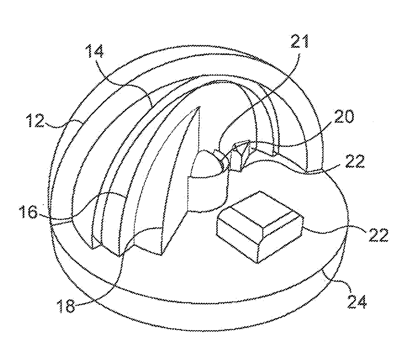
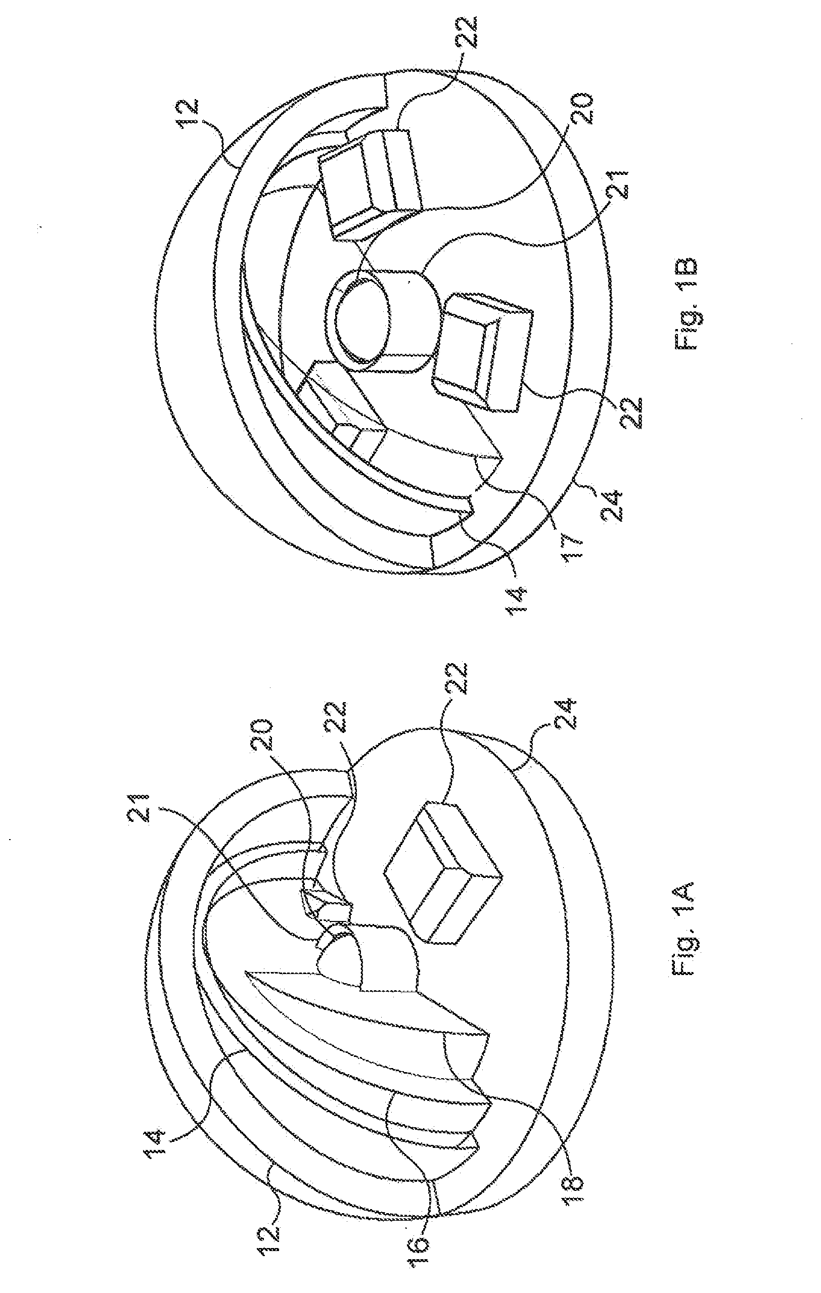
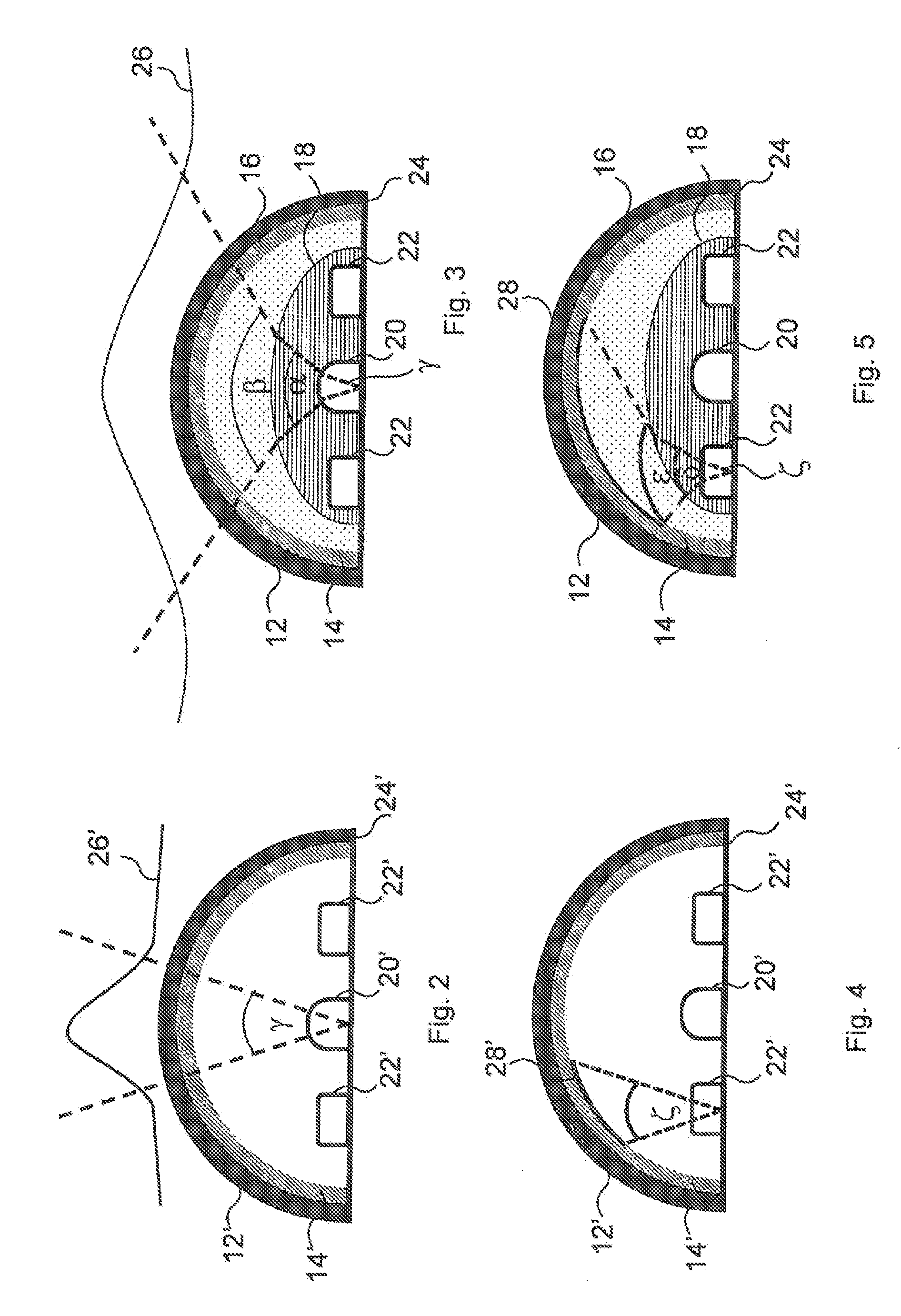
[0045]The sensor device according to the invention operates on the basis of optical principles. FIG. 1A shows the structural view of an embodiment of the sensor device according to the invention. For a better view, the depicted details of various layers of the sensor device are folded out. The sensor device according to the invention comprises a carrier element 24, at least one, in the present embodiment one, light emitting element 20 arranged on the carrier element 24, at least one, in this embodiment three, light detecting element 22 arranged on the carrier element 24, and a cover layer 12 reflecting at least one part of the light emitted by the light emitting element 20 to at least one light detecting element. The carrier element of the sensor device according to the invention has a flat configuration in some of the depicted embodiments. In some preferred embodiments of the sensor device according to the invention, the light emitting element 20 is capable of emitting infrared lig...


PUM

PropertyMeasurementUnit
transparentaaaaaaaaaa
flexibleaaaaaaaaaa
shapeaaaaaaaaaa

Abstract

The invention is a sensor device comprising a carrier element (24), at least one light emitting element (20) arranged on the carrier element (24), at least one light detecting element (22) arranged on the carrier element (24); a cover layer (12) reflecting at least one part of the light emitted by the light emitting element (20) to the at least one light detecting element (22); and at least one transparent filler element (16, 18) filling at least partly the space between the carrier element (24) and the cover layer (12) and being made of a flexible material.

Description

TECHNICAL FIELD[0001]The invention relates to a sensor device. More particularly, the invention relates to a sensor device adapted to sense pressure and force acting on its surface.BACKGROUND ART[0002]Sensory perception plays an increasingly important role in robotics. By means of sensory perception, it is desirable to obtain as much information about the environment as possible to ensure that robots respond optimally. In robotics, the most frequent tasks are gripping, positioning and object relocation. The approaches used so far were indeed feasible in a well-modelled environment, where the position and orientation of the object were known. The robotic arms and gripping devices becoming increasingly widespread which fact led necessarily to the expectation of applying them in as broad a range as possible, and also in an undefined environment. A future goal of robotics is that robots should have similar capabilities to human beings and provide assistance for them. To this end, it is ...

Claims


Application Information

Patent Timeline
Patent Type & Authority Applications(United States)
IPC IPC(8): G01L1/24
CPCG01L1/248G01L5/166G01L1/24
Inventor TAR, KOS SANDORCSEREY, GYORGY GABORVERES, JOZSEF
Owner ONROBOT HUNGARY KFT
Why Eureka
Try Eureka