Radio communication device, radio communication method, and radio communication system

a radio communication system and radio communication technology, applied in the field of radio communication devices, radio communication methods, radio communication systems, can solve the problems of increasing the power consumption whether the comp set of the ue terminal is to be semi-statically or dynamically updated becomes a problem, etc., to suppress the overhead of the ue terminal, improve the frequency of point selection update, and suppress the effect of downlink and uplink overhead

Active Publication Date: 2014-11-06
SONY CORP
View PDF1 Cites 14 Cited by
  • Summary
  • Abstract
  • Description
  • Claims
  • Application Information

AI Technical Summary

Benefits of technology

[0143]According to the technology disclosed in the present specification, it is possible to provide an excellent radio communication device, radio communication method, and radio communication system capable of suppressing downlink and uplink overhead due to reference signals for point selection and of improving a point selection update frequency.
[0144]In addition, according to the technology disclosed in the present specification, it is possible to provide an excellent radio communication device, radio communication method, and radio communication system capable of suppressing power consumption of a UE terminal that performs reference signal measurement and of improving a point selection update frequency.
[0145]Other objects, characteristics, and advantages of the technology disclosed in the present specification will become apparent from the more detailed description based on exemplary embodiments to be described later and the accompanying drawings.

Problems solved by technology

That is, whether the CoMP set of the UE terminal is to be semi-statically or dynamically updated becomes a problem.
In addition, it is necessary to consider an increase in power consumption of the UE terminal due to the frequent measurement of the reference signals by the UE terminal.

Method used


Image

  • Radio communication device, radio communication method, and radio communication system
  • Radio communication device, radio communication method, and radio communication system
  • Radio communication device, radio communication method, and radio communication system

Examples


Embodiment Construction

[0168]Exemplary embodiments of the technology disclosed in the present specification will be described in detail with reference to the drawings.

[0169]LTE is a communication method based on an OFDM modulation method, and OFDMA is employed in a radio access method of downlink. FIG. 21 shows a radio frame configuration of a downlink of LTE. As shown in the drawing, the radio frame is hierarchized into three layers: a time slot layer, a sub-frame layer, and a radio frame layer in ascending order of time unit.

[0170]A 0.5 millisecond time slot is composed of seven OFDM symbols (for normal unicast transmission) and becomes a demodulation processing unit upon reception on the user side (UE terminal). A 1 millisecond sub-frame is composed of two consecutive time slots (fourteen OFDM symbols) and becomes a transmission time unit of one data packet subjected to correction encoding. A 10 millisecond radio frame is composed of ten consecutive sub-frames (that is, twenty time slots) and becomes a...


PUM


Abstract

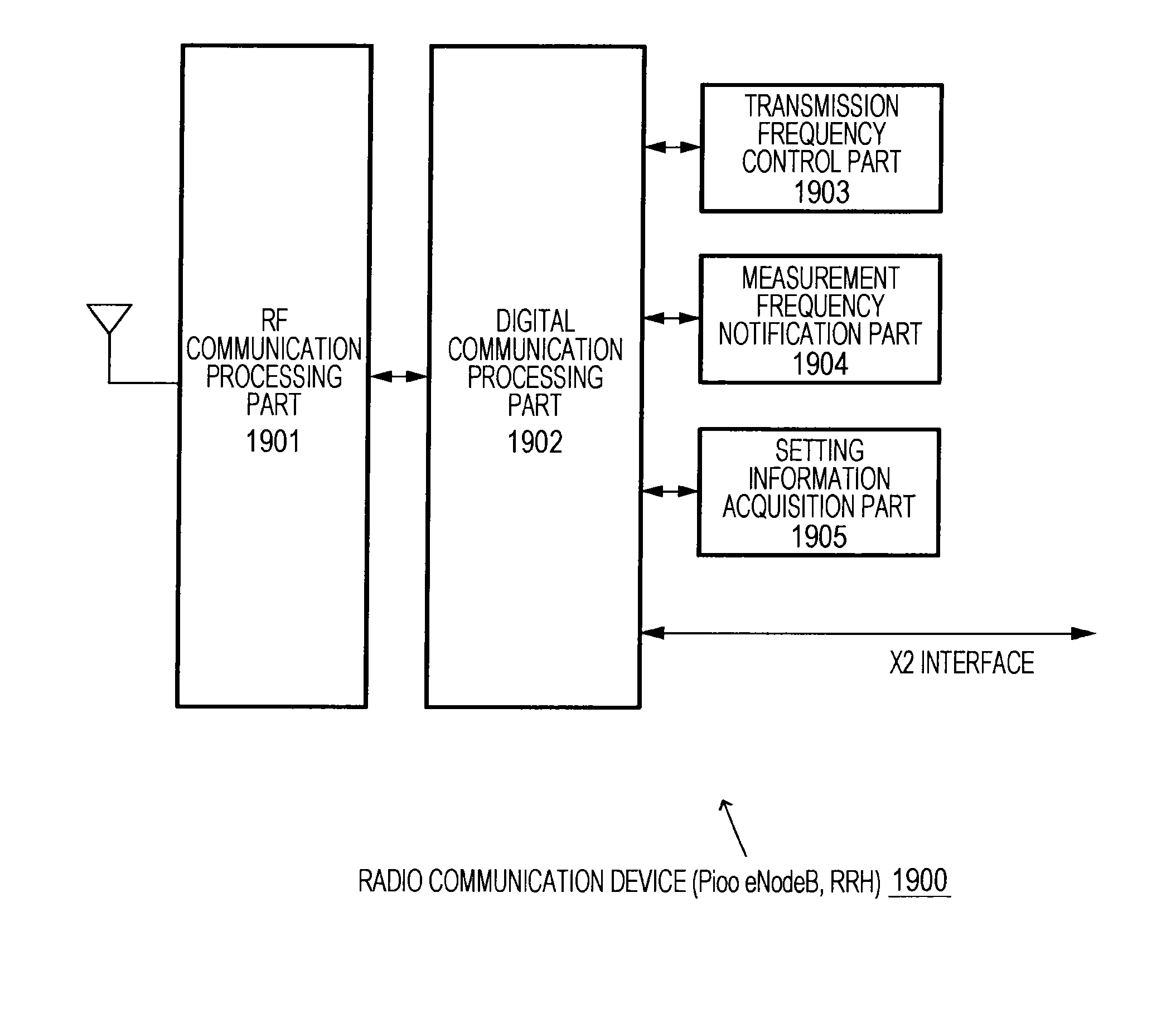
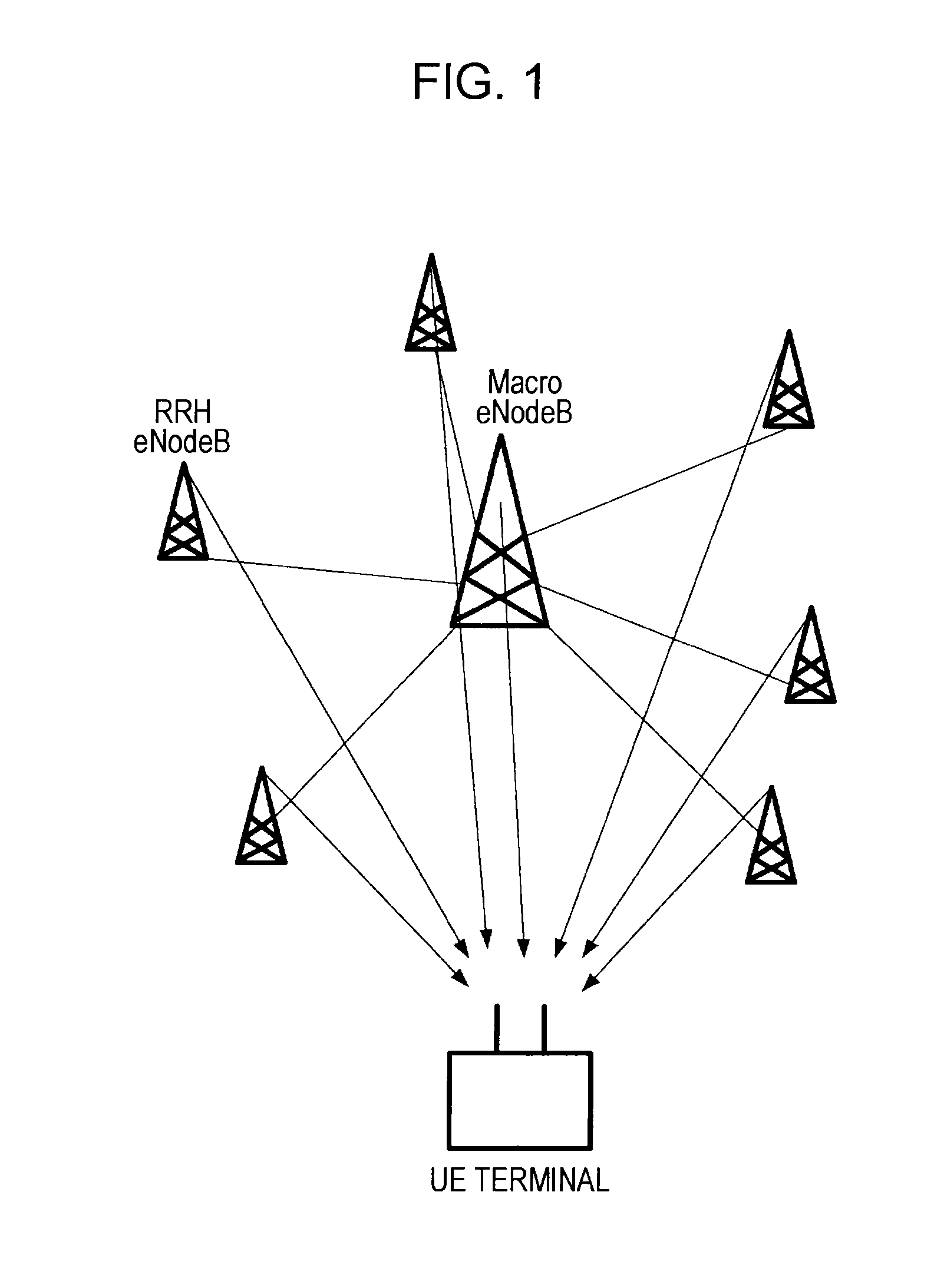
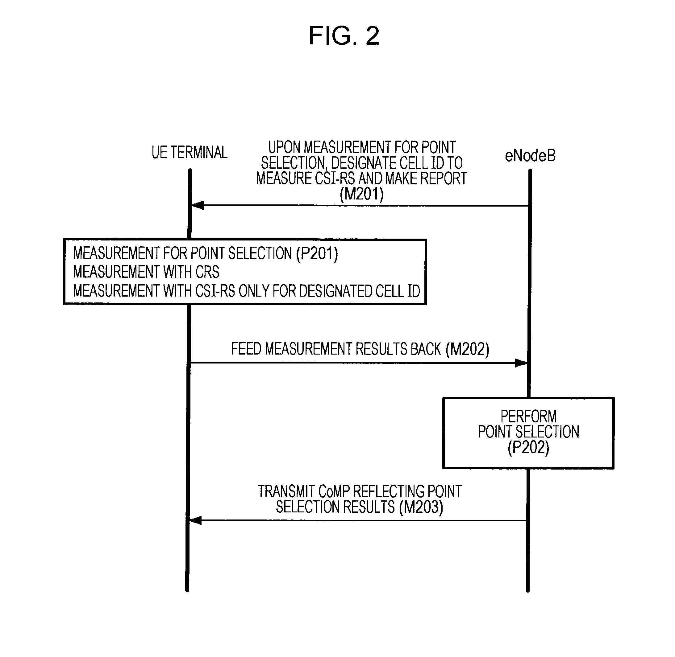
In a radio communication, a UE terminal uses a CSI-RS as a reference signal for point selection only in the case of a scenario 4, and uses a CRS as a reference signal for point selection in the cases of scenarios 1 to 3 other than the scenario 4. Through RRC signaling, an eNodeB notifies the UE terminal of the fact that the measurement of a specific cell ID will be performed using a CSI-RS, that is, a cell ID using a CSI-RS as a reference signal for point selection. The operations suppress overhead of reference signals and improve a point selection update frequency.

Description

TECHNICAL FIELD[0001]The technology disclosed in the present specification relates to a radio communication device, a radio communication method, and a radio communication system adapted to simultaneously transmit and receive data to a terminal in cooperation with another base station, and particularly, to a radio communication device, a radio communication method, and a radio communication system adapted to determine a combination of base stations with respect to a terminal based on feedback from the terminal receiving a reference signal.BACKGROUND ART[0002]Currently, standardization of fourth-generation mobile communication systems is performed in third generation partnership project (3GPP). “Long term evolution (LTE)”, that is one of data communication specifications designed by 3GPP, is a long term advanced system aiming for the fourth generation (4G) IMT-Advanced, and is called “3.9G (super 3G).”[0003]In LTE, two duplex systems, i.e., frequency division duplex (FDD) and time di...

Claims


Application Information

Patent Timeline
Patent Type & Authority Applications(United States)
IPC IPC(8): H04L5/00H04W24/02
CPCH04L5/0035H04W24/02H04B7/024H04L5/001H04L5/005H04L5/0057H04L5/0078H04W16/32H04W48/18
Inventor TAKANO, HIROAKI
Owner SONY CORP
Why Eureka
Try Eureka