Terminal block

a terminal block and insulating plate technology, applied in the direction of coupling device details, coupling device connection, dynamo-electric components, etc., can solve the problems of reducing the insulation reliability of the insulating plate between the terminals, and achieve the effect of preventing a reduction in insulation reliability

Active Publication Date: 2014-11-06
NISSAN MOTOR CO LTD
View PDF10 Cites 7 Cited by
  • Summary
  • Abstract
  • Description
  • Claims
  • Application Information

AI Technical Summary

Benefits of technology

[0005]The present invention was developed in view of the above problem and aims to provide a terminal block in which terminals are housed in a case made of a resin or the like and which can prevent a reduction in insulation reliability due to thermal stress.

Problems solved by technology

Due to the repeat of this thermal stress, the insulating plate may be possibly cracked or damaged, causing a problem of reducing insulation reliability of the insulating plate between the terminals.

Method used


Image

  • Terminal block
  • Terminal block
  • Terminal block

Examples


Embodiment Construction

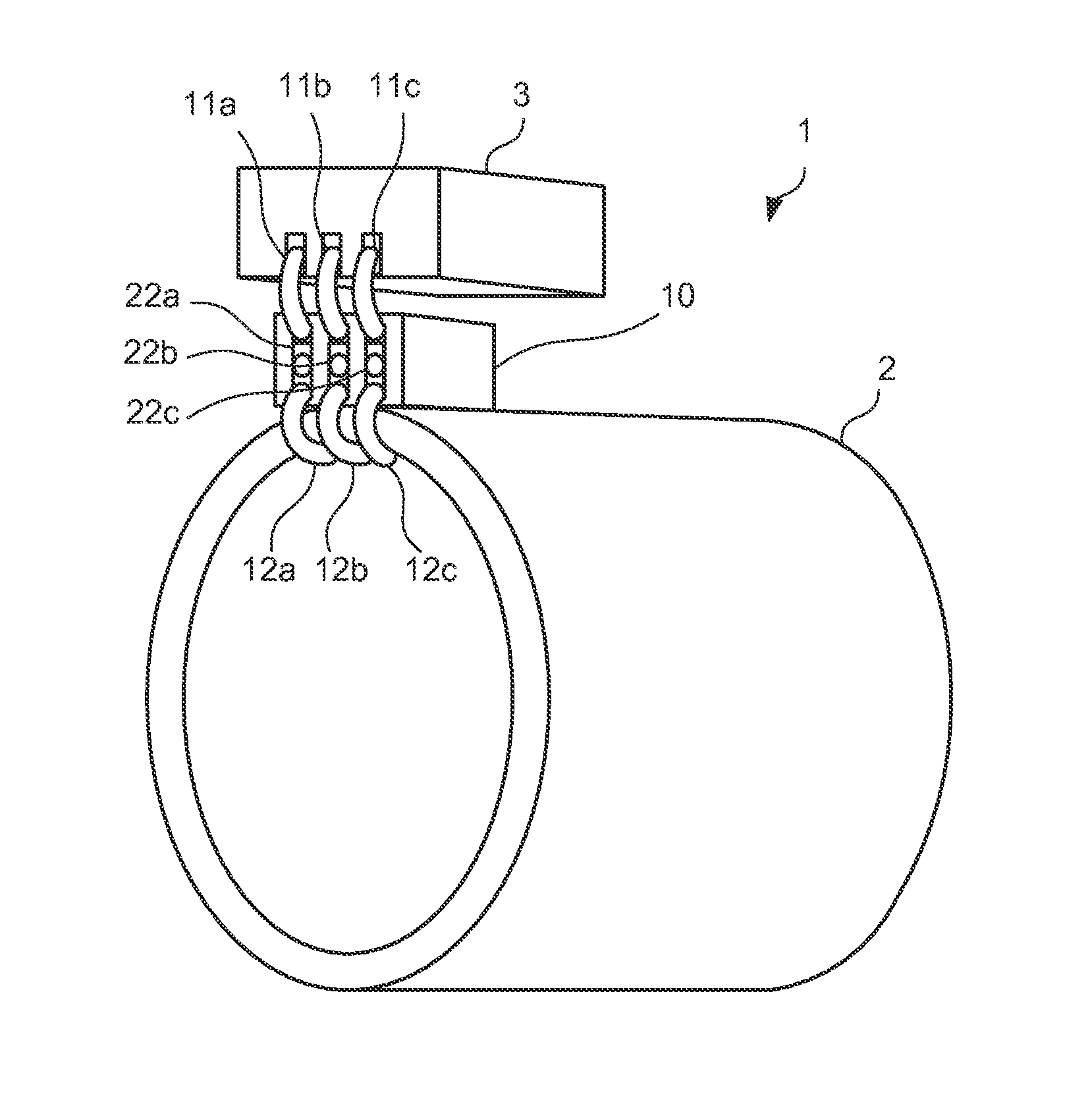
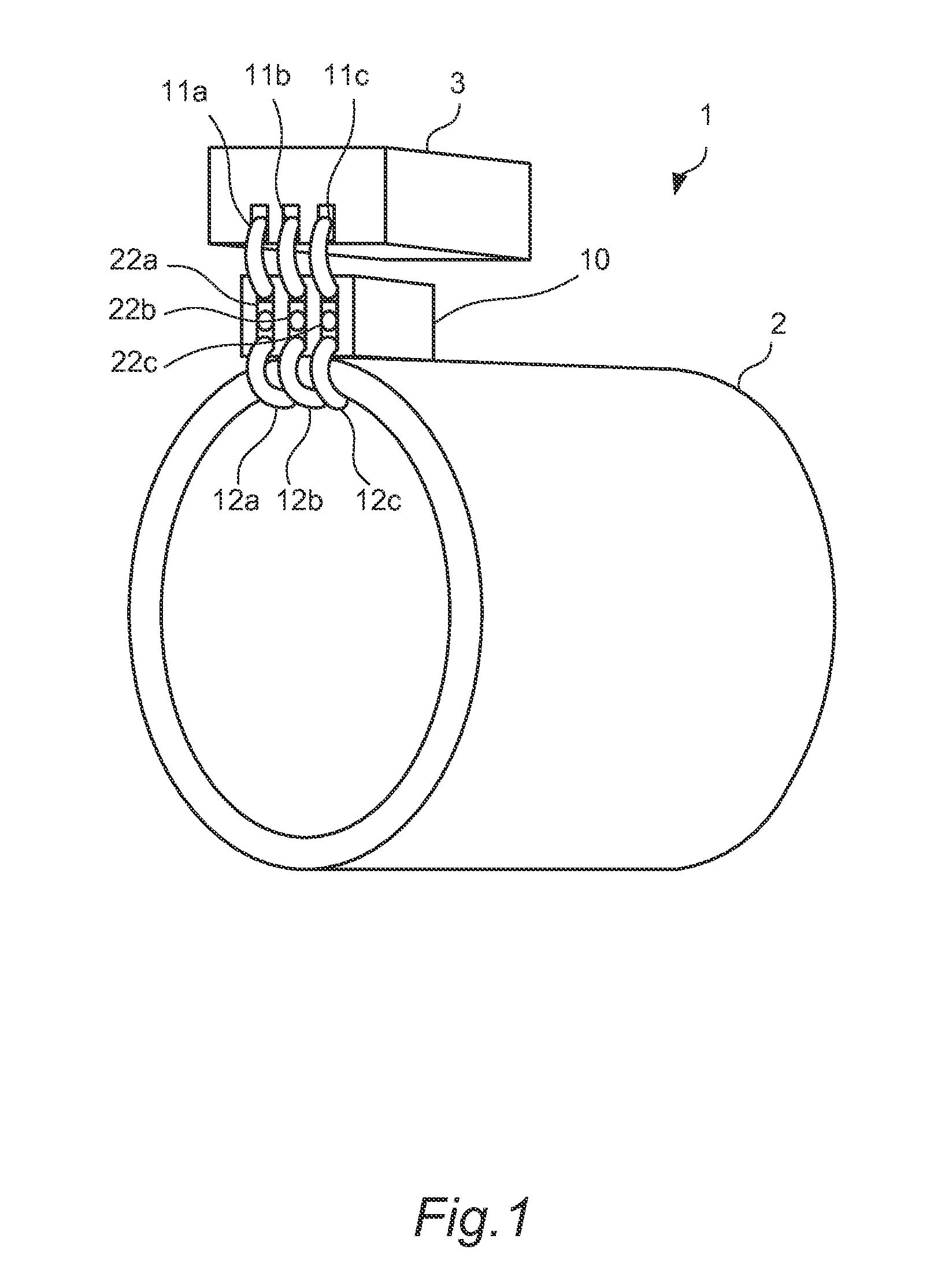
[0022]FIG. 1 is a diagram of a driving device 1 including a terminal block 10 of an embodiment of the present invention.

[0023]The driving device 1 includes a motor 2, an inverter 3 and the terminal block 10 for electrically connecting the motor 2 and the inverter 3.

[0024]The inverter 3 is a power conversion device to which DC power from a DC power source such as an unillustrated battery is input and which supplies power for driving the motor 2 by converting the input DC power into three-phase alternating-current power and supplying it to the motor 2 and receives and supplies regenerative power from the motor 2 to the DC power source.

[0025]The motor 2 is an electric motor including, for example, poles of three phases and rotates a rotor by the application of the three-phase alternating-current power from the inverter 3 to a winding of a stator. Further, regenerative power is generated in the stator by the rotation of the rotor and supplied to the inverter side. The rotor is not shown...


PUM


Abstract

A terminal block for electrically connecting a plurality of first wires connected to an electric motor and a plurality of second wires connected to a power conversion device for supplying drive power of the electric motor includes a case, a plurality of terminals housed in the case and configured to connect the plurality of first wires and the plurality of second wires to each other, a partition wall provided between the plurality of terminals to electrically isolate the plurality of terminals from each other, and plate-like members provided between the partition wall and the terminals and made of a material with a higher elasticity than the case and the partition wall.

Description

TECHNICAL FIELD[0001]The present invention relates to a terminal block for connecting wires.BACKGROUND ART[0002]In an electric motor, a terminal block with a plurality of terminals is used to connect wires connected to a stator winding of each phase and an external power source such as an inverter. Since the terminals need to be insulated from each other, the terminals are generally partitioned by electrically insulating partition plates (hereinafter, insulating plates) made of a resin or the like.[0003]As such a terminal block, JP63-310344A discloses a plastic terminal block integrally molded of an engineering plastic material while including a terminal block and integrally molded with insulating plates for insulating between wires in the terminal block as reinforcement ribs of the terminal box.SUMMARY OF INVENTION[0004]In the case of molding terminals made of a metal by a resin, thermal stress is created in an insulating plate made of an insulating resin between the terminals due ...

Claims


Application Information

Patent Timeline
Patent Type & Authority Applications(United States)
IPC IPC(8): H01R9/24H01R13/514
CPCH01R9/24H01R13/514H01R4/30H01R13/405H02K5/225
Inventor MATSUZAKI, HIROKAZUOKUYAMA, TAKENARI
Owner NISSAN MOTOR CO LTD
Why Eureka
Try Eureka