Front-end Circuit for Band Aggregation Modes

a band aggregation and circuit technology, applied in the field of front-end circuits for band aggregation modes, can solve the problems of unavoidable losses at the front-end, inconvenient construction of front-end circuits with two duplexers, and inconvenient construction of front-end circuits with additional areas

Active Publication Date: 2014-11-06
SNAPTRACK
View PDF9 Cites 82 Cited by
  • Summary
  • Abstract
  • Description
  • Claims
  • Application Information

AI Technical Summary

Benefits of technology

[0005]Embodiments of the present invention provide a front-end circuit that can be used for band aggregation operation modes, that does not provide performance degradation and that does not require developing new components like filters and duplexers.

Problems solved by technology

Up to now, no technical solution is known how to construct a front-end circuit with two duplexers that can be operated without any performance degradation or without any additional requirements on the duplexers.
Such a matching unavoidably incurs losses at the front-end but also requires additional area on the front-end.
If the existing front-end already supports several band combinations, this would make the design challenging and prone to yield loss.
Secondly, the single duplexers need to have an extremely good out-of-band reflectivity so that the duplexers are not loading each other, which otherwise would increase RF front-end losses significantly.
Further, as known front-ends use different filter technologies in one module, these losses cannot be compensated within a module design.
Even lossless matching components cannot solve this task if using a known architecture of the front-end.

Method used


Image

  • Front-end Circuit for Band Aggregation Modes
  • Front-end Circuit for Band Aggregation Modes
  • Front-end Circuit for Band Aggregation Modes

Examples


first embodiment

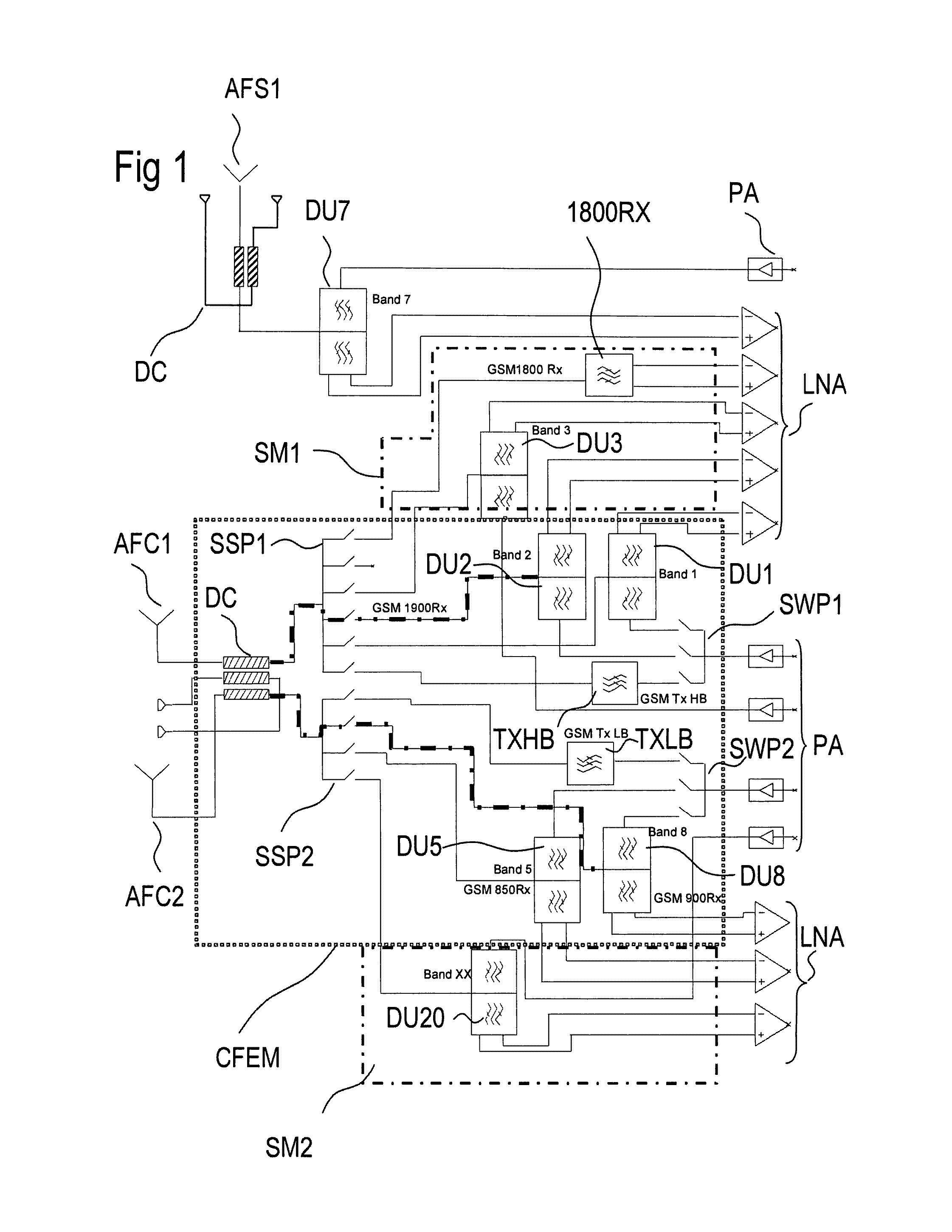
[0032]FIG. 1 shows a first embodiment according to the invention comprising a core front-end module CFEM with two core antenna feeds AFC1 and AFC2. Each antenna feed of the core front-end module is connected to a separate switch SSP1, SSP2 allowing to connect the respective switch with a desired signal path. A duplexer DU1 for band 1 and another duplexer DU2 for band 2 are connected to the first switch SSP1. Further, a Tx path comprising a Tx filter TXHB for GSM high-band operation is coupled to the first switch SSP1. Coupled to the second switch SSP2 are a third duplexer DU5 for band 5 operation and a fourth duplexer DU8 for band 8 operation. Further, a Tx filter TXLB for GSM low-band operation is coupled to the second switch SSP2. As the two duplexers DU1, DU2 and the Tx high-band filter TXHB for GSM are assigned to a frequency range that is usually named “high-band” comprising a frequency range between about 1.7-2.2 GHz, all Tx paths for this high-band can be connected to a first...

embodiment 1

[0058]All components like filters, duplexers, antenna switches and amplifier switches may be located and integrated on the same front-end module. Similar referring to FIG. 1, it is possible to position some of the signal paths in supplemental modules that are electrically connected to the core front-end module by one of the antenna switches. In all cases, only those components are coupled to the same antenna switch and thus the same antenna feed that are within the same frequency range. Systems that can produce intermodulation products disturbing the operation in other frequency bands are located in external signal paths, being coupled to a separate antenna, as shown in this embodiment for band 7 and band 11 duplexers.

second embodiment

[0059]According to the first and second embodiment, simultaneous operation is possible between all systems coupled to different antenna feeds. As shown in FIG. 3, simultaneous operation is possible also with the help of additional matching networks (e.g., MC1 and MC2 required for Band 2 and Band 4 carrier aggregation).Hence, aggregated operation modes are possible allowing to receive and operate Rx signals in different frequency ranges (or similar frequency ranges, see FIG. 3) at the same time. In an analog way, simultaneous Tx transmission in different frequency ranges is possible, too. A Tx band aggregation for the LTE standard is not yet defined but may be a future option which can be operated in an embodiment according to the invention.

[0060]FIG. 4 shows a third embodiment that is similar to the first embodiment shown in FIG. 1 and comprises one common antenna feed AF1 and one common antenna for the 1 GHz and 2 GHz frequency ranges. The two paths of the high-band and low-band ar...


PUM


Abstract

A front-end circuit for a wireless communication unit includes at least two antenna feeds. At least one of the antennas is coupled to an antenna switch. The circuit comprises filters and duplexers and is prepared to operate a number of FDD frequency bands. Each FDD band comprises an Rx band for receive signals and a Tx band for transmit signals. The circuit provides a single band operation mode for each frequency band and aggregated band operation modes. In an aggregated band operation mode Rx signals can be received in two different frequency bands at the same time as well as Tx signals can be transmitted in at least one of the two different frequency bands. In addition, TDD bands as well as GSM bands are covered.

Description

[0001]This patent application is a national phase filing under section 371 of PCT / EP2011 / 066543, filed Sep. 22, 2011, which is incorporated herein by reference in its entirety.TECHNICAL FIELD[0002]Embodiments of the present invention relate to a front-end circuit for band aggregation modes.BACKGROUND[0003]Currently, the new cellular mobile communication standard LTE (long term evolution) is being implemented globally. As one main new feature, this standard comprises the possibility to use two receive channels at the same time at different frequency bands to improve the downlink data rata. According to the newest releases to this standard, a series of inter-band combinations are defined each comprising two Rx frequency bands in which receive signals have to be operated at the same time by a mobile phone. In the LTE standard, the combination of different frequency bands, in the following called band aggregation, concerns up to now FDD (Frequency Division Duplexing) frequency bands onl...

Claims


Application Information

Patent Timeline
Patent Type & Authority Applications(United States)
IPC IPC(8): H04B1/40H04B7/04H04L5/14
CPCH04B1/40H04B7/04H04L5/14H04B1/006H04B1/0064H04B1/52
Inventor ELLA, JUHAIKONEN, PEKKASCHMIDHAMMER, EDGARTIKKA, PASI
Owner SNAPTRACK
Why Eureka
Try Eureka