Infinitely variable transmissions, continuously variable transmissions, methods, assemblies, subassemblies, and components therefor

a transmission and infinitely variable technology, applied in the field of transmissions, can solve the problems that the transmission cannot deliver intermediate speed ratios such as 1:1.5, 1:1.75, 1.5:1, or 1.75

Active Publication Date: 2014-11-06
FALLBROOK INTPROP COMPANY
View PDF5 Cites 84 Cited by
  • Summary
  • Abstract
  • Description
  • Claims
  • Application Information

AI Technical Summary

Benefits of technology

[0009]The systems and methods herein described have several features, no single one of which is solely responsible for its desirable attributes. Without limiting the scope as expressed by the claims that follow, its more prominent features will now be discussed bri

Problems solved by technology

For example, such a transmission may provide for a speed ratio of 1:2, 1:1, or 2:1, but such a transm

Method used


Image

  • Infinitely variable transmissions, continuously variable transmissions, methods, assemblies, subassemblies, and components therefor
  • Infinitely variable transmissions, continuously variable transmissions, methods, assemblies, subassemblies, and components therefor
  • Infinitely variable transmissions, continuously variable transmissions, methods, assemblies, subassemblies, and components therefor

Examples


Embodiment Construction

” one will understand how the features of the system and methods provide several advantages over traditional systems and methods.

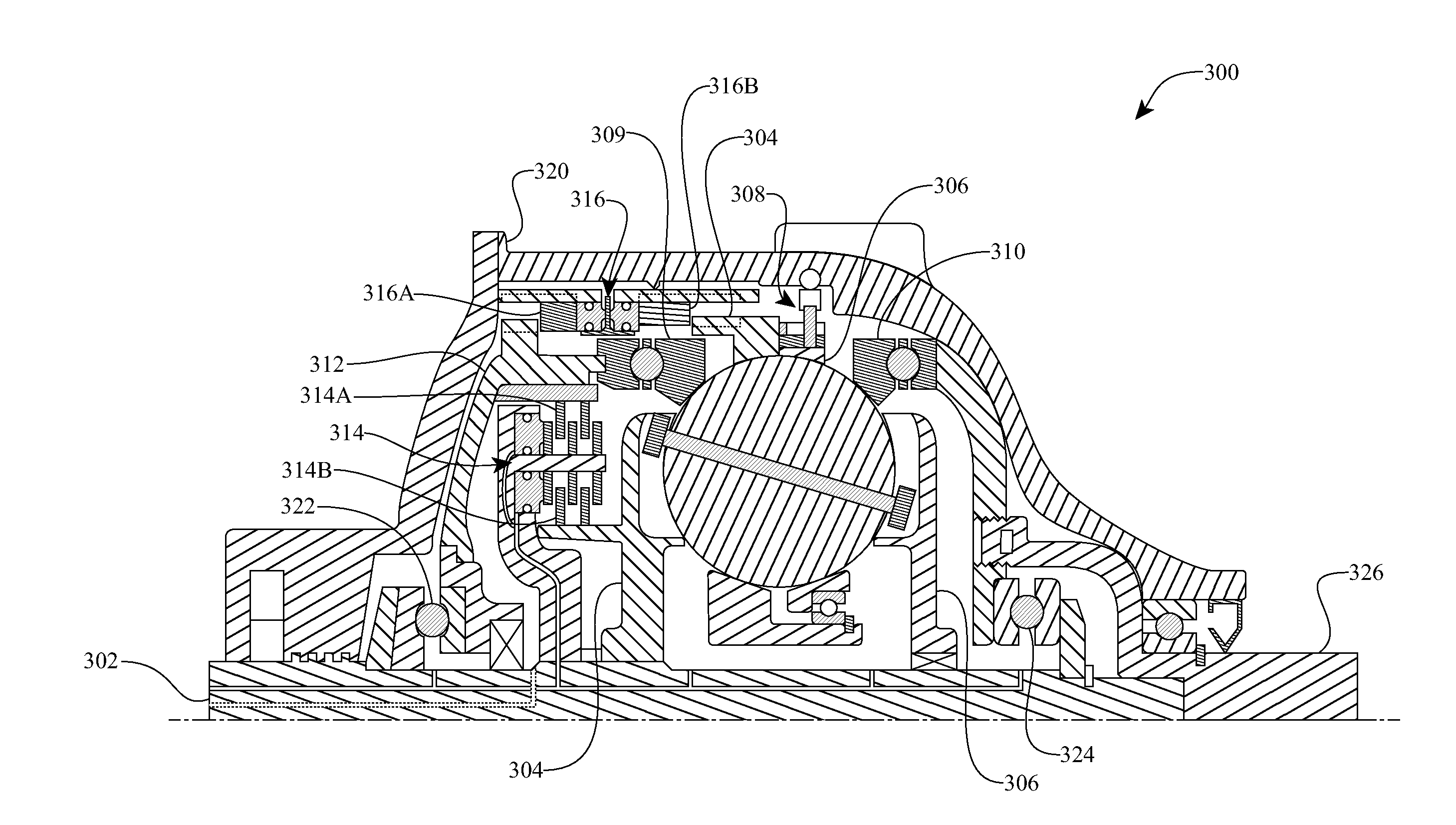
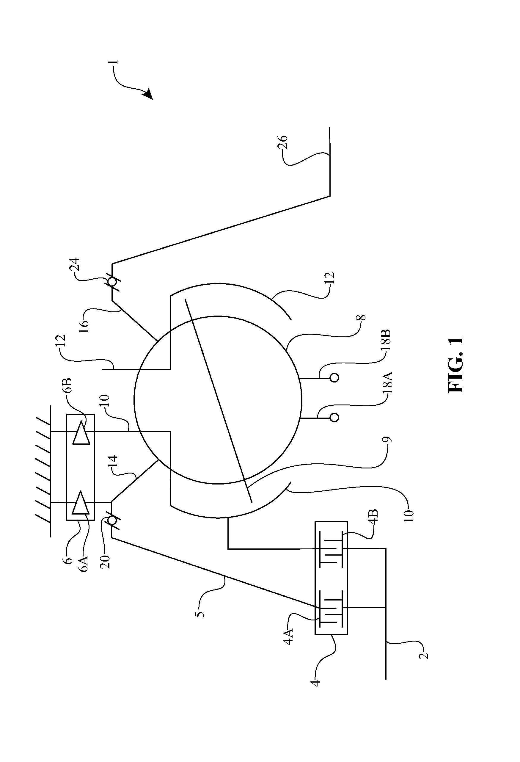
[0010]One aspect of the disclosure relates to a transmission having a first disc mounted coaxially about a longitudinal axis of the transmission, a number of tiltable balls placed angularly about the longitudinal axis and in contact with the first disc, and a second disc mounted coaxially about the longitudinal axis of the transmission and in contact with the plurality of tiltable balls. In one embodiment, the transmission is provided with an idler placed radially inward of, and in contact with, the tiltable balls. The transmission has a cage operably coupled to the balls. In one embodiment, the transmission has a first clutch assembly operably coupled to the cage and the first disc. The transmission is provided with a second clutch assembly operably coupled to the cage and the first disc. At least two of the first disc, second disc, idler, and cage are ad...


PUM


Abstract

Inventive embodiments are directed to components, subassemblies, systems, and/or methods for infinitely variable transmissions (IVT). In one embodiment, a control system is adapted to facilitate a change in operating mode of an IVT. In another embodiment, a control system includes a drive clutch coupled to a source of rotational power; the drive clutch is configured to selectively engage a traction ring and a carrier of the IVT. The control system includes a one-way clutch assembly configured to selectively engage the traction ring and the carrier. In some embodiments, the control system governs the actuation of the one-way clutch to selectively lock and unlock components of the IVT. In some embodiments, the control system implements an IVT mode wherein the carrier selectively couples to a source of rotational power. In other embodiments, the control system implements a CVT mode wherein the traction ring selectively couples to a source of rotational power.

Description

CROSS REFERENCE TO RELATED APPLICATIONS[0001]This application is a continuation of International Application No. PCT / US2013 / 022419, filed Jan. 21, 2013, which claims the benefit of U.S. Provisional Patent Application No. 61 / 589,765, filed on Jan. 23, 2012. The disclosures of all of the above-referenced prior applications, publications, and patents are considered part of the disclosure of this application, and are incorporated by reference herein in their entirety.BACKGROUND OF THE INVENTION[0002]1. Field of the Invention[0003]This disclosure relates generally to transmissions, and more particularly the embodiments related to continuously variable transmissions (CVTs) and infinitely variable transmissions (IVTs).[0004]2. Description of the Related Art[0005]In certain systems, power is characterized by torque and rotational speed. More specifically, power in these systems is generally defined as the product of torque and rotational speed. Typically, a transmission couples to a power i...

Claims


Application Information

Patent Timeline
IPC IPC(8): F16H15/40
CPCF16H15/40F16H15/52B62M11/12F16H15/28F16H15/503F16H61/664
Inventor THOMASSY, FERNAND A.SMITHSON, ROBERTJACKSON, DAVID BRIANLOHR, III, CHARLES B.
Owner FALLBROOK INTPROP COMPANY
Why Eureka
Try Eureka