Operations Monitoring in an Area

a technology for monitoring operations and areas, applied in the direction of instruments, television systems, image enhancement, etc., can solve problems such as serious consequences, and achieve the effect of accurate determination of the three-dimensional location of targets

Active Publication Date: 2014-11-13
INT ELECTRONICS MACHINES
View PDF5 Cites 42 Cited by
  • Summary
  • Abstract
  • Description
  • Claims
  • Application Information

AI Technical Summary

Benefits of technology

[0007]Aspects of the invention provide a solution for monitoring an area including one or more restricted zones. The solution can include one or more monitoring assemblies deployed to acquire image data of the area and independently monitor operations within the area at each monitoring assembly. A monitoring assembly can include one or more local alert components to generate an audible or visual alarm to local personnel. Data regarding static features present in the area can be used to create a registration map of the field of view, which can subsequently enable accurate determination of the three-dimensional location of a target using two-dimensional image data and / or identify an extent of a restricted zone even when one or more of the static features are obscured. Monitoring a target over a series of images can be used to determine whether an alert condition is present.

Problems solved by technology

The inventors recognize several limitations in previous approaches for monitoring operations over a large area, such as a railroad yard, an airport, an industrial loading area, or other locations in which mistakes or failures during the operations can lead to serious consequences.

Method used


Image

  • Operations Monitoring in an Area
  • Operations Monitoring in an Area
  • Operations Monitoring in an Area

Examples


Embodiment Construction

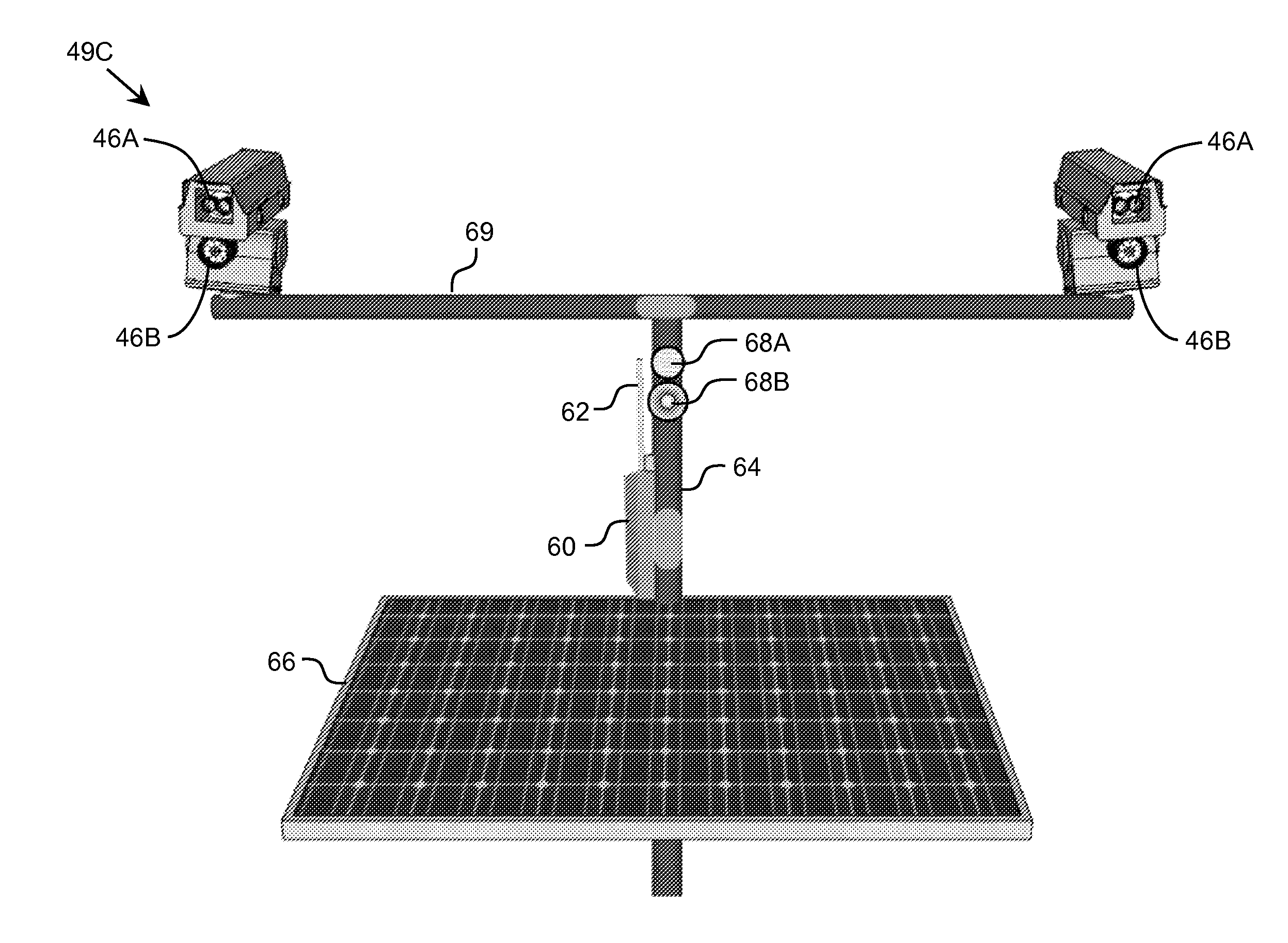
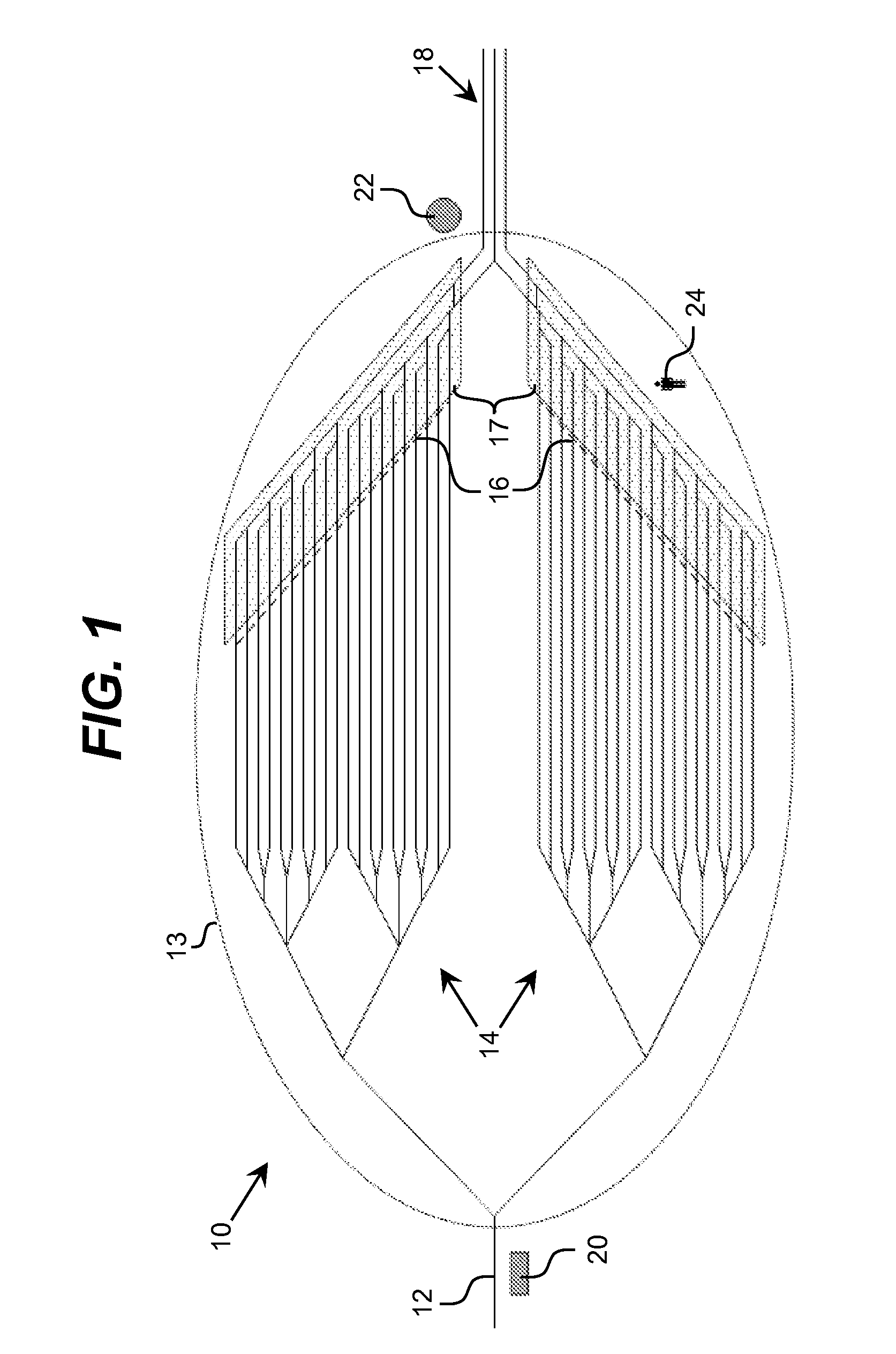
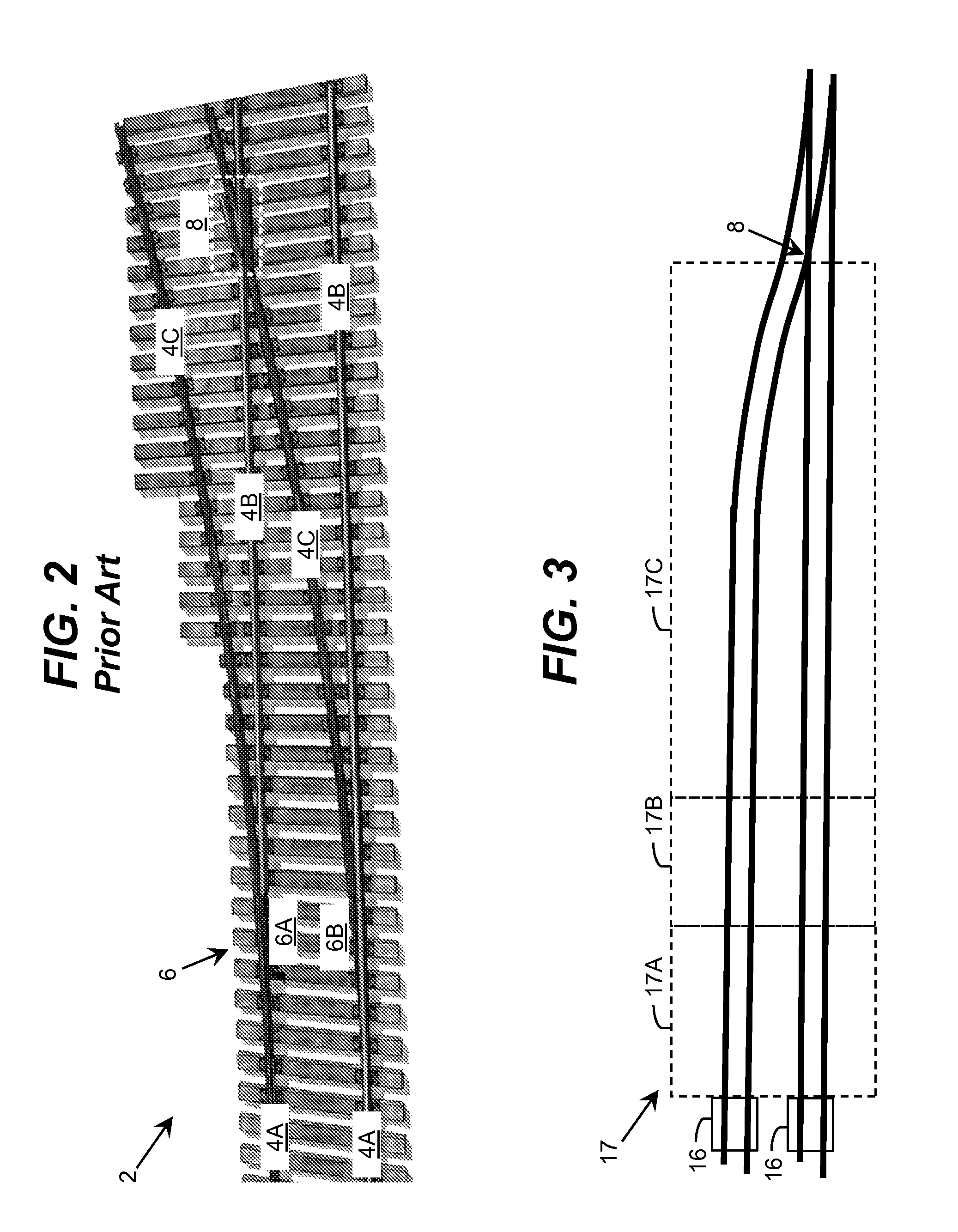
[0024]Embodiments of the invention can provide one or more improvements over prior art approaches for monitoring areas. Illustrative improvements include, for example, using ambient features of a monitored area to determine three-dimensional distance from two-dimensional image data; use of multispectral data fusion to disambiguate an alert situation from normal operations; use of near-infrared image data with selective filtering to increase contrast in bad weather and eliminate interference from sunlight, fixed background lights, moving headlights, and the like; situation analysis based on analysis of a series of images (e.g., blob tracking); autonomous smart camera assemblies which can be capable of independent operations as well as networked communications; and / or the like.

[0025]As indicated above, aspects of the invention provide a solution for monitoring an area including one or more restricted zones. The solution can include one or more monitoring assemblies deployed to acquire...


PUM


Abstract

A solution for monitoring an area including one or more restricted zones is provided. The solution can include one or more monitoring assemblies deployed to acquire image data of the area and independently monitor operations within the area at each monitoring assembly. A monitoring assembly can include one or more local alert components to generate an audible or visual alarm to local personnel. Data regarding static features present in the area can be used to create a registration map of the field of view, which can subsequently enable accurate determination of the three-dimensional location of a target using two-dimensional image data and/or identify an extent of a restricted zone even when one or more of the static features are obscured. Monitoring a target over a series of images can be used to determine whether an alert condition is present.

Description

REFERENCE TO RELATED APPLICATIONS[0001]The current application claims the benefit of co-pending U.S. Provisional Application No. 61 / 855,074, titled “Smart area operations monitor,” which was filed on 8 May 2013, and which is hereby incorporated by reference.TECHNICAL FIELD[0002]The disclosure relates generally to monitoring operations in an area, and more particularly, to monitoring vehicle movements in an area.BACKGROUND ART[0003]It is often desirable to monitor operations over a large area, such as a railroad yard, an airport, an industrial loading area, and / or the like, where mistakes or failures during the operations can lead to serious consequences. Current approaches for monitoring operations in such areas utilize one of two basic approaches. By far the most common, which is currently in use in most rail settings, airports, and similar locations, uses human “spotters.” A spotter is a person whose sole or partial function is to observe the operations of the area and recognize a...

Claims


Application Information

Patent Timeline
Patent Type & Authority Applications(United States)
IPC IPC(8): B61L23/00G06T7/00G06K9/00H04N7/18H04N5/33
CPCB61L23/00H04N7/181H04N5/33G06K9/00651G06T7/0042G06T2207/10048G06T2207/10004G06T2207/30236G06T2207/30232B61L17/00B61L17/02B61L23/041G06T2207/10021G06T7/55G06V20/54B61L27/40
Inventor MIAN, ZAHID F.GAMACHE, RONALD W.
Owner INT ELECTRONICS MACHINES
Why Eureka
Try Eureka