Needle holder

a needle holder and needle technology, applied in the field of needle holder, can solve the problems of inability to abort and significant problems for users, and achieve the effect of increasing the range of needle size and sufficient toleran

Active Publication Date: 2014-11-13
NEORAD BV
View PDF2 Cites 29 Cited by
  • Summary
  • Abstract
  • Description
  • Claims
  • Application Information

AI Technical Summary

Benefits of technology

[0013]The needle holder preferably comprises a base for supporting the needle holder on the patient's body. Advantageously, the lateral movement of the clip and / or the guide arrangement is a movement of the clip and / or the guide arrangement without requiring movement of the needle relative to a base of the needle holder. Although in some instances it may be beneficial to move the base away from the patient's body as the needle is disconnected, it will often be desirable to disconnect the needle without movement of the needle relative to the body. By using an arrangement that does not require movement of the base relative to the needle, both the base and the needle can remain in situ as the clip is released. Once disconnected from the needle, the needle holder can be easily removed.
[0033]It will be appreciated that different interventional procedures require different sizes of needle. The clip of the present invention may be made with sufficient tolerance to accommodate a range of needle sizes. In a preferred embodiment, a number of clips for fitment to different sizes of needle are provided in order to allow an increased range of needle size. Advantageously, the different sizes of clip may be used with the same guide arrangement, as the clips can be disengaged and replaced. Hence, the invention extends to a needle holder kit comprising a needle holder as set out above, with a clip for needles of first size, and at least one additional releasable clip, the additional clip being for needles of a second, different, size. There may also be one or more further additional clips, for needles of a third, different, size, a fourth, different, size and so on. Multiple clips of each size may be provided. This will enable use of the needle holder with multiple needles of each different size.

Problems solved by technology

The inventors have realised that this creates significant problems for the user, as it means that the user cannot abort the use of the needle holder without retracting the needle from the patient.

Method used


Image

  • Needle holder
  • Needle holder
  • Needle holder

Examples


second embodiment

[0060]The first channel 31 and third channel 34 of the clip 3 of the second embodiment can be seen in more detail in FIG. 8. The first channel 31 includes two ridges 35, and the third channel 34 includes two wedge shaped portions 36. These wedges 36 increase in width toward the middle of the clip 3. The second channel 32 intersects both the first and the third channels. The first channel 31 is narrower than the third channel 34, such that the second channel 32 extends beyond a side edge 37 of the first channel 31 to form a recess for the needle 6. The third channel 34 is wider, and a side edge 38 of the third channel 34 forms a continuous surface with the base of the second channel 32.

[0061]Operation of this clip 3 can be seen in FIGS. 9 to 11, which show detail of the clip 3 in cross-section for two positions in the first orientation, and also in the second orientation.

[0062]In FIG. 9 the clip is in the first orientation (as in FIG. 6), and hence the first channel 31 is engaged wit...

first embodiment

[0064]As for the first embodiment, the clip 3 is composed of a resilient material, so it can be released from the rail portion 22 by pressing the two upper portions of the outer flanges together, which form lever portions for moving the two lower portions apart and widening either the first channel 31 or the third channel 34, depending on the orientation of the clip 3.

[0065]The needle holder would typically be supplied sterilised and packed in a sterilised pouch for single use, and use of the needle holder might proceed as follows:

[0066]1. Clean, disinfect and cover the chosen entry point in a conventional manner.

[0067]2. Unpack the needle holder.

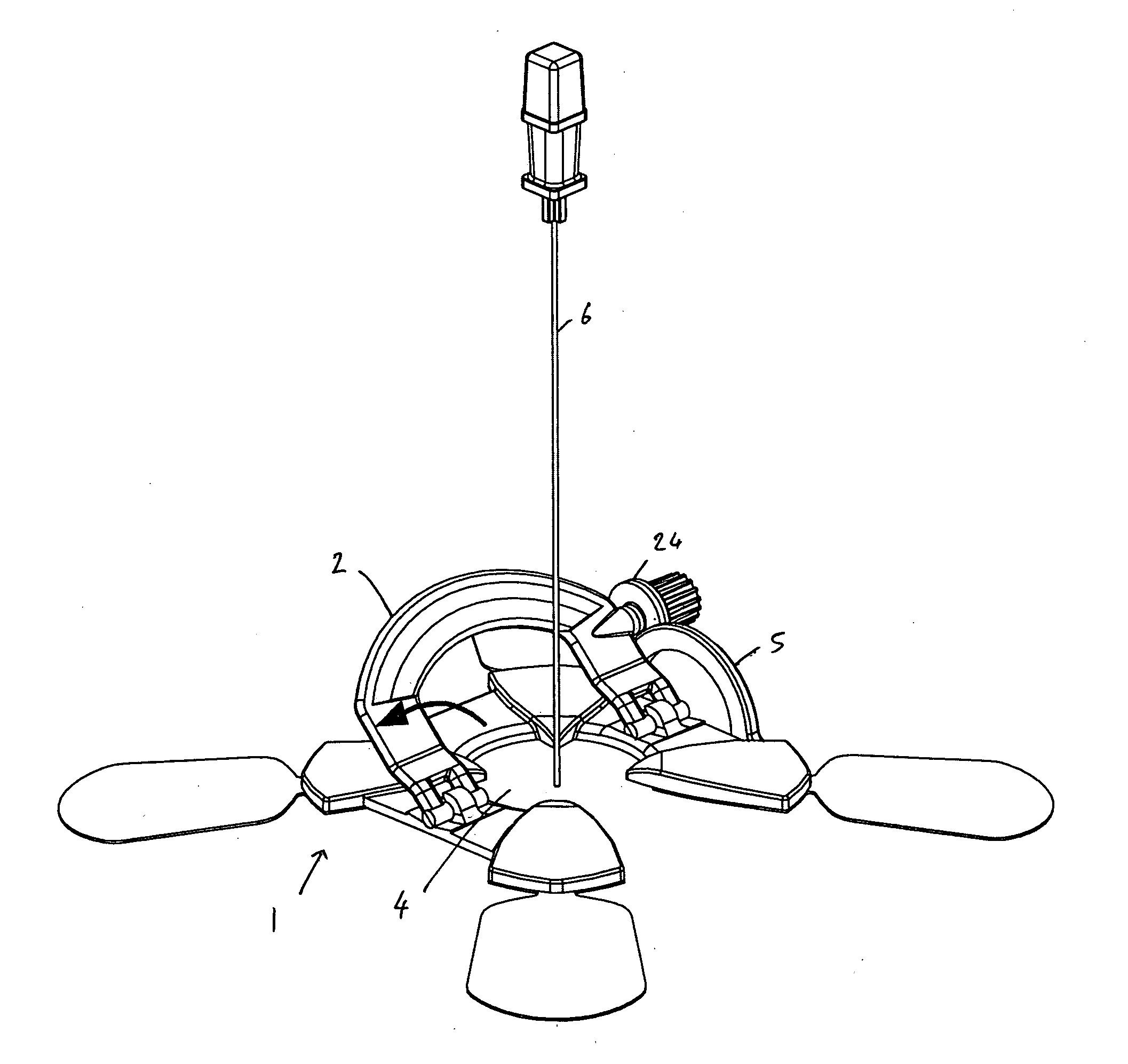
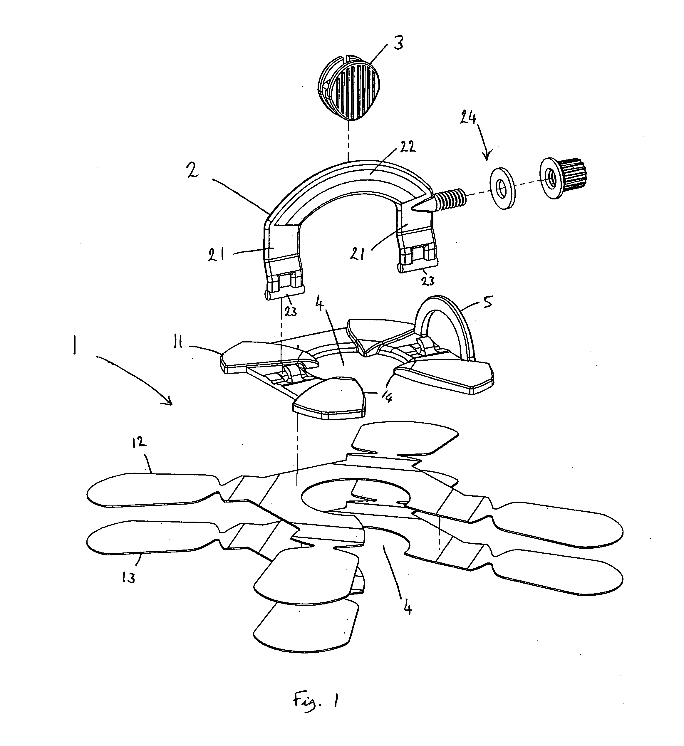
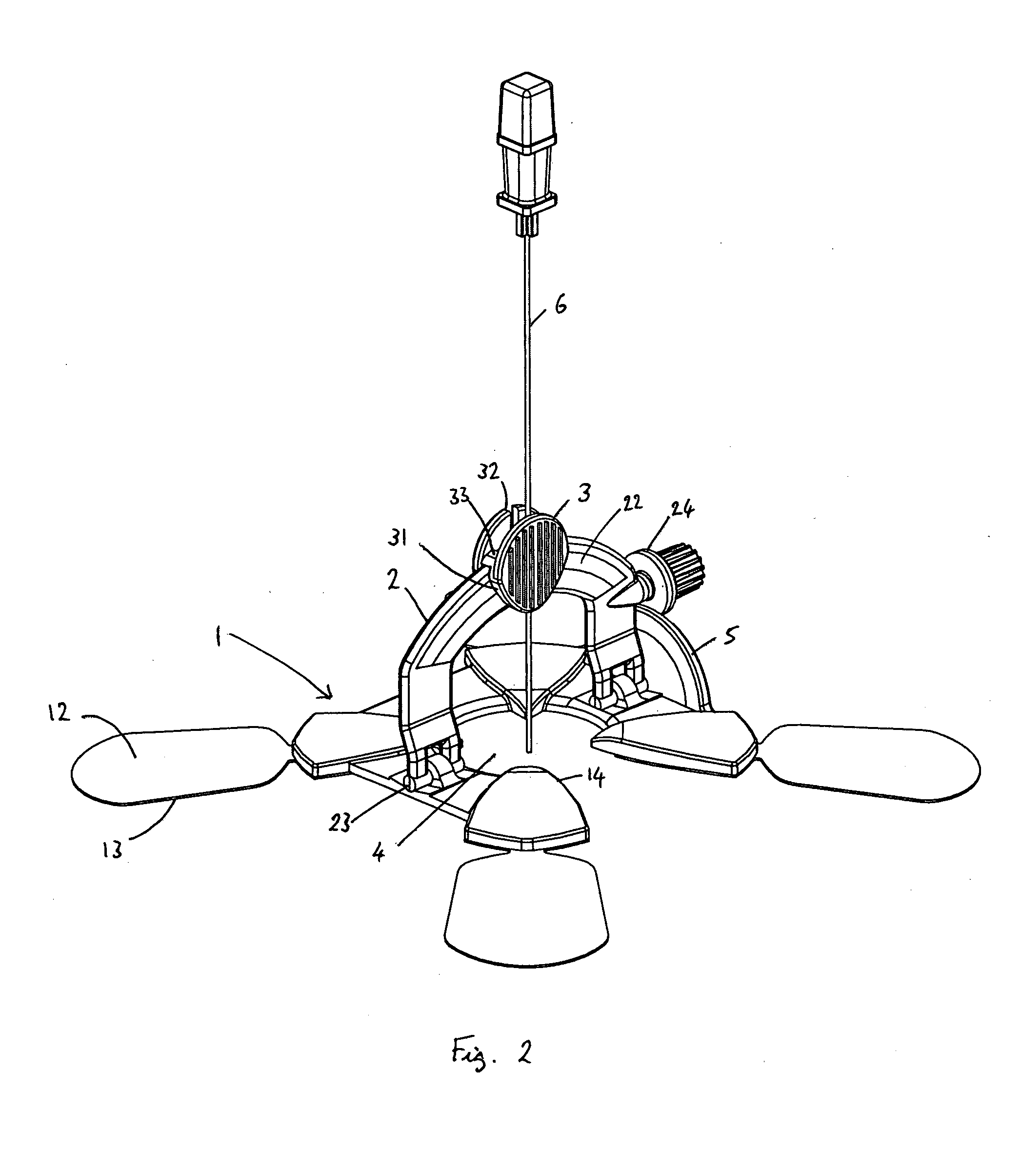
[0068]3. Centre the needle holder over the entry point using the four arrows 14 in the base plate 11 or markers located on the arrows 14. If a needle 6 is already in place locate the needle holder around it and centre the base 1 over the entry point.

[0069]4. Raise the first guide member 2 until it supports the needle 6 and fasten the screw ...


PUM


Abstract

A needle holder for use in an image guided intervention procedure. The needle holder includes a clip for holding a needle and a guide arrangement for supporting the clip and directing the needle at a desired angle relative to a patient's body. The clip includes a releasable connection such that the needle can be disengaged from the guide arrangement by a lateral movement of the clip and / or the guide arrangement relative to the longitudinal axis of the needle.

Description

RELATED APPLICATIONS[0001]The present application is a continuation of U.S. Ser. No. 13 / 144,107, filed on Sep. 28, 2011. U.S. Ser. No. 13 / 144,107 is incorporated herein by reference in full. The present application likewise claims priority to International Application No. PCT / GB2010 / 000101, filed on Jan. 21, 2010; U.S. Provisional Serial No. 61 / 206,326, filed on Jan. 28, 2009; and GB 0901072.9, filed on Jan. 22, 2009. These applications are incorporated herein by reference in full.TECHNICAL FIELD[0002]The invention relates to a needle holder for use in image guided interventions.BACKGROUND OF THE INVENTION[0003]Interventional radiology is a subspecialty of radiology in which minimally invasive procedures are performed using image guidance. Some of these procedures are done for purely diagnostic purposes (e.g., biopsy), while others are done for treatment purposes (e.g., radio frequency ablation). Pictures (images) are used to direct these procedures, which are usually done with need...

Claims


Application Information

Patent Timeline
Patent Type & Authority Applications(United States)
IPC IPC(8): A61B19/00A61B17/34
CPCA61B19/201A61B17/3403A61B2017/3405A61B2017/3407
Inventor BRABRAND, KNUTBERARD-ANDERSEN, NICOLAYOLSEN, GJERMUND FJELDBAKKE, VEGARD
Owner NEORAD BV
Why Eureka
Try Eureka