

Apparatus for Linear Friction Welding
a technology of friction welding and apparatus, applied in the direction of soldering apparatus, manufacturing tools, auxillary welding devices, etc., can solve the problem that lfw has not been practical for repair welds
- Summary
- Abstract
- Description
- Claims
- Application Information
AI Technical Summary
Benefits of technology
Problems solved by technology
Method used
Image

Examples
first embodiment
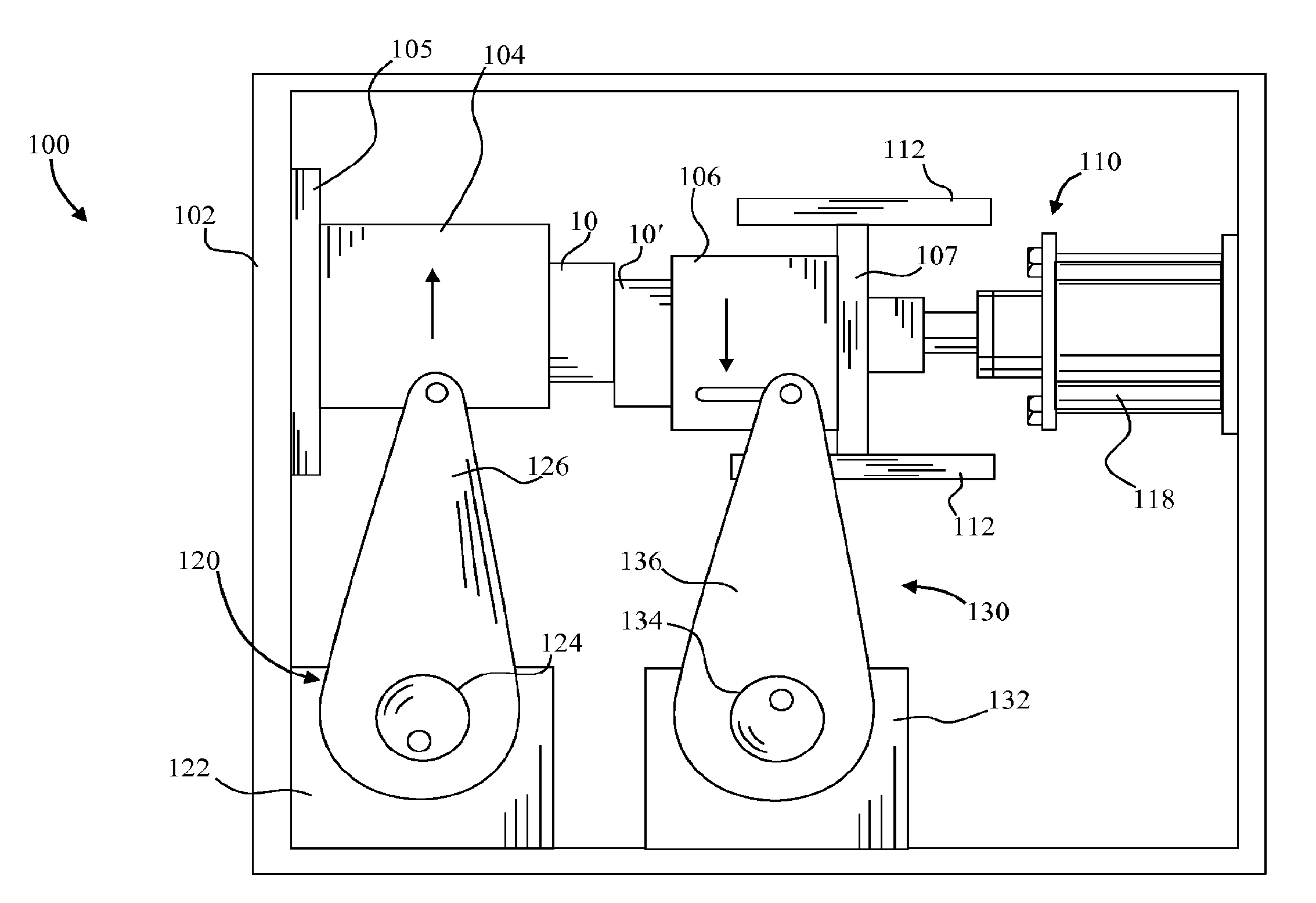
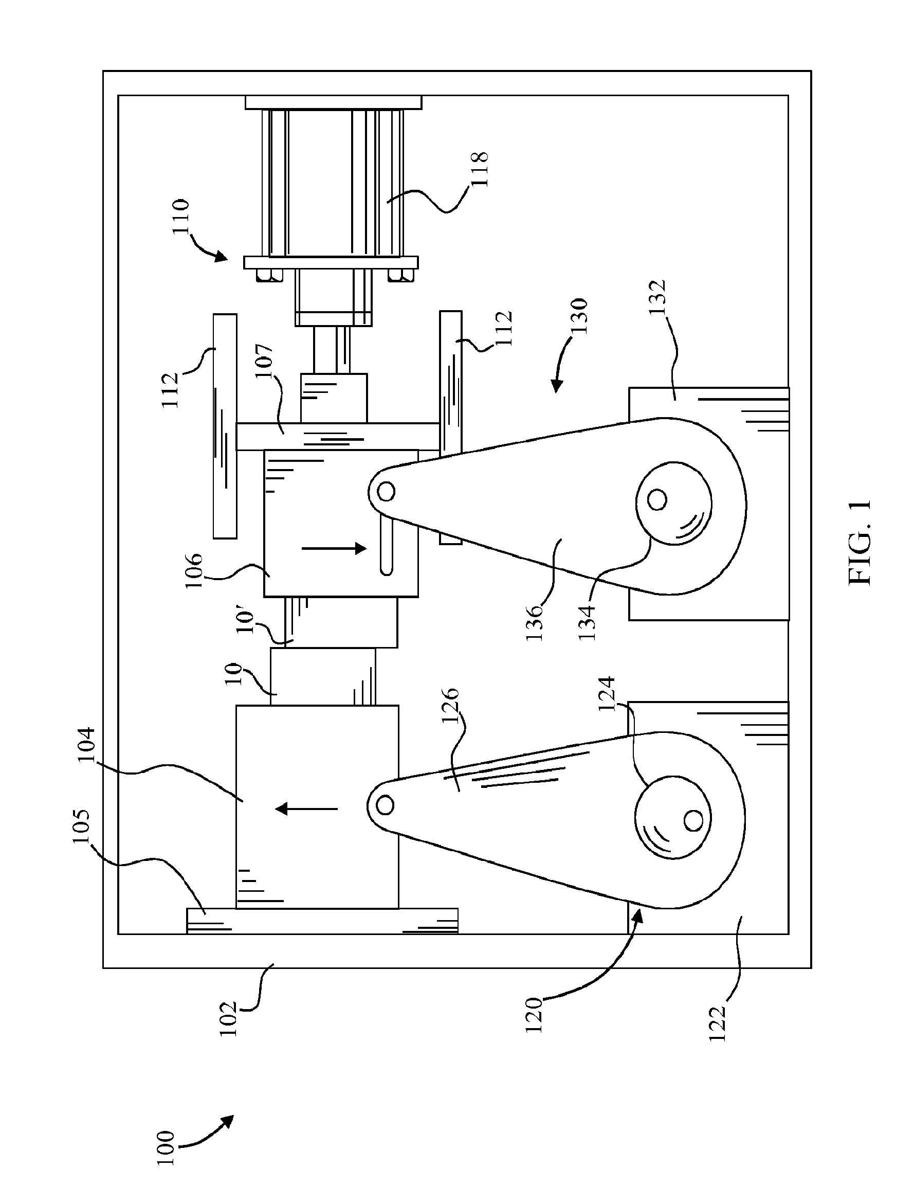
[0013]FIG. 1 illustrates an embodiment of the linear friction welding (LFW) apparatus of this invention, which is designated as reference number 100. LFW apparatus 100 includes two mounting fixtures 104 and 106 that securely hold work pieces 10 and 10′ during the weld process. Mounting fixtures 102 and 104 may take any suitable form or configuration depending on the size, shape and configuration of the work pieces being welding in any particular application. As shown, fixture 104 rides on slides 105 mounted to frame 102 to facilitate the transverse motion of work piece 10 along the weld axis. Similarly fixture 106 rides on slides 107 to facilitate the transverse motion of work piece 10′ along the same weld axis. LFW apparatus 100 includes a press assembly 110 that forcibly moves fixture 106 toward fixture 102 to apply the weld and forging pressures to work pieces 10 and 10′ during the welding process. As shown, press assembly 110 includes slides 112 which shiftably support fixture 1...
second embodiment
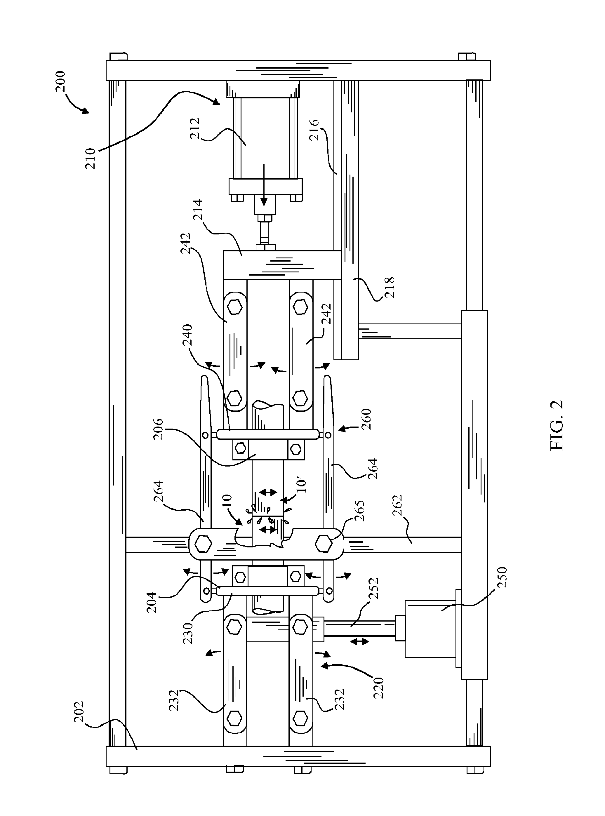
[0015]FIGS. 2 and 3 illustrate another embodiment of the linear friction welding LFW) apparatus, which is designated as reference number 200. LFW apparatus 200 uses a single oscillator and two sets of rocker arm supported carriages operatively connected by a linkage mechanism to simultaneously vibrate both work pieces 10 and 10′ along a single weld axis. The dual sets of rocker arm supported carriages connected by the linkage mechanism generates the relative movement between the work pieces, which provides a mechanical advantage over a single oscillator vibrating assembly.
[0016]As shown, LFW apparatus 200 includes two mounting fixtures 204 and 206 that securely hold work pieces 10 and 10′ during the weld process. As with the LFW apparatus 100, mounting fixtures 204 and 206 may take any suitable form or configuration depending on the size, shape and configuration of the work pieces being welded in any particular application. Fixtures 204 and 206 are operatively connected to vibrating...
third embodiment
[0017]FIGS. 4-6 illustrate a third embodiment of the linear friction welding LFW) apparatus, which is designated as reference number 300. Again, LFW apparatus 300 uses a single oscillator and two sets of rocker arm supported carriages operatively connected by a linkage mechanism to simultaneously vibrate both work pieces 10 and 10′ along a single weld axis. The dual sets of rocker arm supported carriages are connected by the linkage mechanism, which generates the relative movement between the work pieces, which provides a mechanical advantage over a single oscillator vibrating assembly.
[0018]As shown, LFW apparatus 300 includes a frame 302, which supports press assembly 310 and vibrating assembly 320. Two mounting fixtures 304 and 306 that securely hold work pieces 10 and 10′ during the weld process are mounted to carriages 330 and 340, respectively. As with the LFW apparatus 100, mounting fixtures 306 and 308 may take any suitable form or configuration depending on the size, shape ...
PUM
| Property | Measurement | Unit |
|---|---|---|
| force | aaaaa | aaaaa |
| friction | aaaaa | aaaaa |
| pressure | aaaaa | aaaaa |
Abstract
Description
Claims
Application Information