FSW tool

Inactive Publication Date: 2004-10-07
ANDERSSON CLAES GORAN +1
View PDF7 Cites 39 Cited by
  • Summary
  • Abstract
  • Description
  • Claims
  • Application Information

AI Technical Summary

Problems solved by technology

Generally one may say for friction stir welding that the thickness of the metal / alloy to be joined increases it becomes more difficult to achieve a weld of good integrity.
For welding thicker plates of 15 mm up to 25 mm in a single pass, the thickness varying between 15 to 25 mm probes of the type having a 1:1 length / diameter could be used, however these probes tend to displace an excessive amount of material.
As the plates grow thicker scaled-up probes of know simple parallel probe type will displace increasing amounts of material and trials have shown that this is not a recommended way of solving the problem.
However, the welding of thicker materials will necessitate a higher input of pressure put on the probe indicating that it may be a problem to lengthen the probe without making it wider in order to maintain strength.
One of the problems experienced during the plunge sequence is that much of the heat generated is rapidly conducted away from the weld zone through the bulk of the copper causing the tool to lock and then shear off.
This is particularly true when tool probes are manufactured from alloys which have limited ductility such as cemented carbides or ceramics.
A further problem encountered when attempting to weld thicker workpieces of approximately 50 mm thickness are voids created in the weld in the proximity of the proximal end of the probe close to the surface, probably created by non-uniform flow around the used probe.
However increasing the rotation speed above 400 rev / min rapidly increases the temperature of the top surface of the work pieces causing that to become extremely soft before the underlying copper becomes sufficiently soften to for welding to take place.
This situation may cause the shoulder of the tool to penetrate or plunge over an excessive distance into the softened top surface layer.
Firstly, it leaves no room for the plasticized material to be welded, to aggregate after a trailing edge in a probe having a fluted design.
However, the probe shown in FIG. 2 has shown some disadvantages when attempting to make friction stir welds in copper workpieces of considerable thickness, e.g. approximately 50 mm.
These created voids in the plasticized material may, when the weld has cooled remain as a fault in the structure weakening the weld.

Method used


Image

  • FSW tool
  • FSW tool
  • FSW tool

Examples


Embodiment Construction

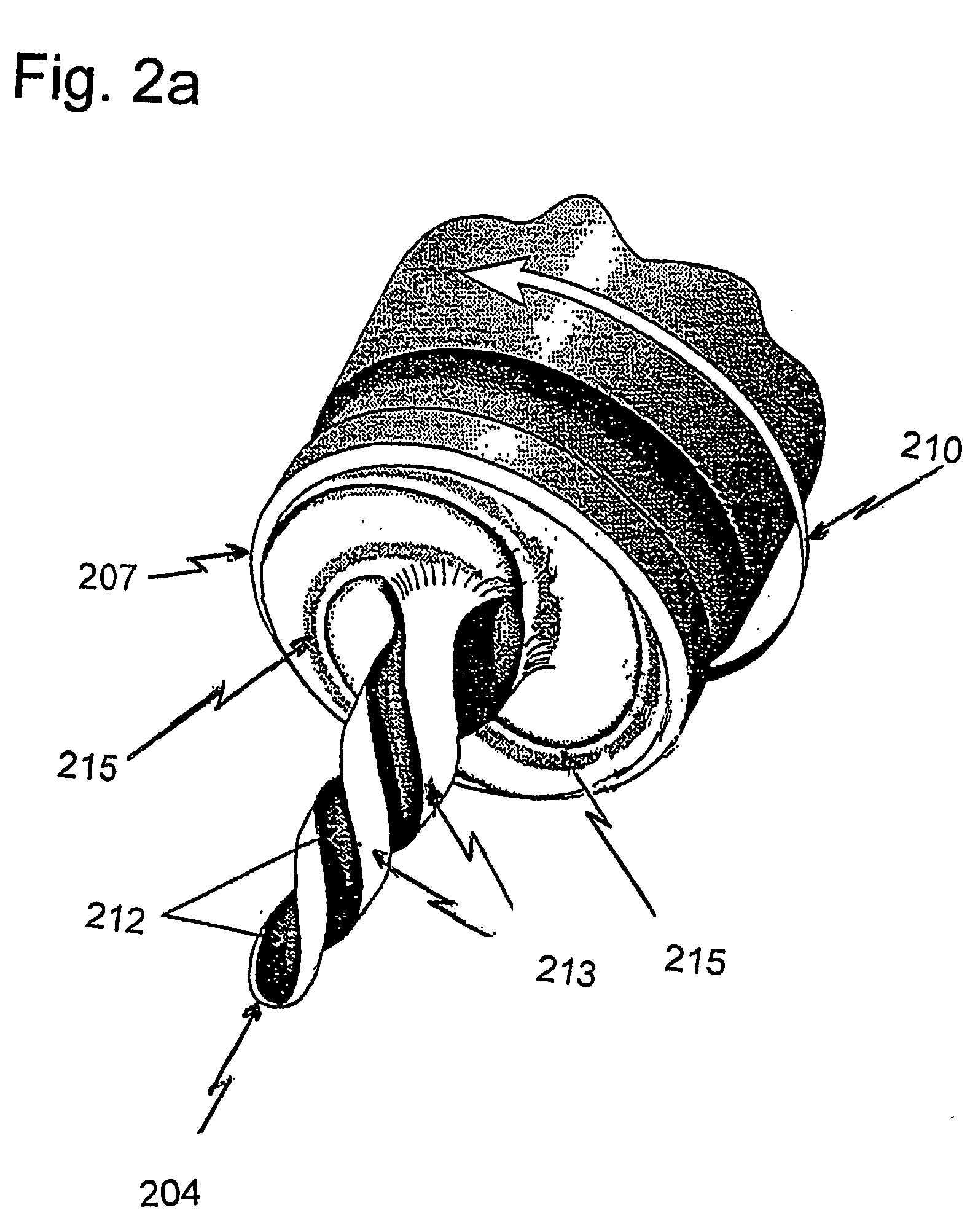
[0047] In FIG. 5a a probe 504 according to the invention is shown. The probe is adapted to be fit into a holder (not shown) by providing a flat portion of the shaft of the probe. A shoulder (not shown) to be used in connection with the probe may be provided on the holder, alternatively on the probe itself.

[0048] The probe and the holder including an appropriate shoulder may of course be manufactured in one piece as the man skilled in the art will appreciate.

[0049] The probe 504 as shown exhibits three helically pitched surfaces 512. However, the form of these surfaces differ essentially from the flutes shown in the prior art probes. The lands or ridges 513 according to the prior art have become thin ridges 513, the surface of which is essentially parallel with the axis of rotation 407 of the probe and a land 523 between each ridge 513 and the adjacent helically pitched surface 512 is also essentially parallel with the axis of rotation 507 of the probe. The lands 523 exhibit thin hel...


PUM

PropertyMeasurementUnit
Angleaaaaaaaaaa
Angleaaaaaaaaaa
Angleaaaaaaaaaa

Abstract

The invention resides in a friction stir welding tool comprising a shaft (532) and a tapered probe (504), said probe having a plurality of helically pitched surfaces (512) extending in the direction from the proximal end (530) of the probe to a distal end (531) of the probe, such that the diameter of the probe, in every longitudinal cross-section of the probe (504), diminishes continously from the proximal end (530) to the distal end (531) of the probe.

Description

[0001] The present invention relates to friction stir welding tools, more particularly it relates to an improved probe.DESCRIPTION OF RELATED ART[0002] Friction stir welding represents a relatively new welding technique. The technique has been developed for welding metals and alloys which have proved difficult to join using conventional fusion welding techniques on account of e.g. thickness of the metal / alloy to be joined or simply metals / alloys that are difficult to weld and require special shielding gases. Flaws that are normally associated with fusion welding such as porosity or solidification cracking may be avoided as a weld cools down.[0003] Generally one may say for friction stir welding that the thickness of the metal / alloy to be joined increases it becomes more difficult to achieve a weld of good integrity.[0004] In friction stir welding a rotating shouldered cylindrical tool, as shown in FIG. 1a, is used to create mechanical friction in the metal in contact with the rapidl...

Claims


Application Information

Patent Timeline
IPC IPC(8): B23K20/12
CPCB23K20/1255B23K20/12
Inventor ANDERSSON, CLAES-GORANANDREWS, DICK R.E.
Owner ANDERSSON CLAES GORAN
Why Eureka
Try Eureka