Double-side symmetric friction stir welding method

A technology of friction stir and welding method, which is applied in welding equipment, non-electric welding equipment, metal processing equipment, etc. It can solve the problems of asymmetry in structure and mechanical properties, easy fracture of stirring needle, and low performance of joints, so as to improve the mechanical properties of joints , avoid root defects, eliminate the effect of asymmetry

Inactive Publication Date: 2012-07-25
HARBIN INST OF TECH
View PDF6 Cites 41 Cited by
  • Summary
  • Abstract
  • Description
  • Claims
  • Application Information

AI Technical Summary

Problems solved by technology

[0004] The invention solves the technical problems of asymmetric structure and mechanical properties of single-sided friction stir welding joints, root defects, difficulty in clamping, self

Method used


Image

  • Double-side symmetric friction stir welding method
  • Double-side symmetric friction stir welding method
  • Double-side symmetric friction stir welding method

Examples


specific Embodiment approach 1

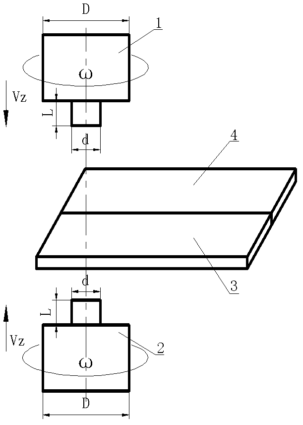
[0013] Specific implementation mode 1: The double-sided symmetric friction stir welding method of this implementation mode is as follows:

[0014] 1. Fix the first workpiece 3 to be welded and the second workpiece 4 to be welded on the workbench with fixtures, so that the first workpiece to be welded 3 and the second workpiece to be welded 4 are docked and at the same level;

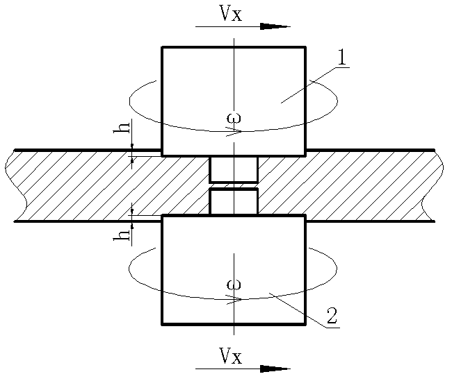
[0015] 2. Insert the stirring head 1 and the stirring head 2 from the upper and lower surfaces of the first welded workpiece 3 and the second welded workpiece 4 at the same rotational speed ω and the same rotational direction respectively at the same piercing speed v z Into the welding starting position between the first workpiece 3 and the second workpiece 4 to be welded, the shoulder surfaces of the stirring head 1 and the stirring head 2 are pressed into the gap between the first workpiece 3 and the second workpiece 4 to be welded The depth is h;

[0016] 3. Stirring head 1 and stirring head 2 use th...

specific Embodiment approach 2

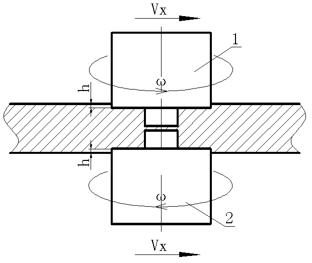
[0018] Embodiment 2: This embodiment differs from Embodiment 1 in that the geometric dimensions of the stirring head 1 and the stirring head 2 in step 2 are the same. Others are the same as in the first embodiment.

specific Embodiment approach 3

[0019] Specific embodiment 3: The difference between this embodiment and specific embodiment 1 or 2 is that the stirring head 1 and the stirring head 2 described in step 2 are in a symmetrical position relative to the first welded workpiece 3 and the second welded workpiece 4 . Others are the same as in the first or second embodiment.


PUM


Abstract

The invention relates to a friction stir welding method, in particular to a double-side symmetric friction stir welding method, which solves the technical problems of asymmetric structure and mechanical properties, root defects, difficulty in clamping, easiness in breakage of a self-sustaining friction stir welding stirring pin, and low welding efficiency and joint property of a single-side friction stir welding joint. The method includes: firstly, fixing workpieces to be welded onto a worktable and positioning the workpieces on the same horizontal plane; secondly, plunging two stirring heads into the two workpieces respectively at the same rotation speed omega in the same or opposite rotation directions to reach preset positions; and thirdly, welding the workpieces to be welded by the aid of the two stirring heads at the same welding speed. By means of adjusting the rotation directions of an upper shaft shoulder and a lower shaft shoulder, flow of materials can be improved, functional asymmetry of heat engines on two sides of the cross section of a joint is eliminated, the mechanical property of the joint is improved, the two stirring heads are used for acting on the upper surfaces and the lower surfaces of the workpieces to be welded respectively to avoid the root defects, and the two stirring heads simultaneously generate heat so that welding efficiency can be remarkably improved.

Description

technical field [0001] The invention relates to a friction stir welding method. Background technique [0002] Friction stir welding (FSW) is a new solid-phase joining technology developed by the British Welding Institute (TWI) in 1991. Compared with traditional fusion welding, it has the advantages of high welding quality, low production cost and no environmental pollution. Has been successfully used in aerospace, aircraft manufacturing and railway transportation and other fields. This welding method is often carried out on one side of the material to be welded, so it is called single-sided friction stir welding. The disadvantage of single-sided friction stir welding is that the shoulder of the stirring head only acts on the upper surface of the workpiece during the welding process, resulting in the thermal mechanical action of the welded material in the thickness direction and the asymmetry of the weld shape, thereby reducing the mechanical properties of the joint ; On th...

Claims


Application Information

Patent Timeline
IPC IPC(8): B23K20/12
Inventor 赵运强刘会杰李金全侯军才
Owner HARBIN INST OF TECH
Why Eureka
Try Eureka