Friction stir welding method and apparatus, and welded structure

a friction stir welding and friction stir technology, applied in the direction of soldering apparatus, manufacturing tools, auxillary welding devices, etc., can solve the problems of inability to join arbitrary curved surfaces having a three-dimensional shape, inability to determine a specific direction, and inability to join arbitrary curved surfaces of a three-dimensional shap

Inactive Publication Date: 2002-10-10
HITACHI LTD
View PDF0 Cites 38 Cited by
  • Summary
  • Abstract
  • Description
  • Claims
  • Application Information

AI Technical Summary

Problems solved by technology

A problem found in Japanese Patent Laid-Open No. 2000-135575 is that workpieces can be joined together if they are flat plate-like, i.e., if the surfaces to be joined are flat surfaces, but that arbitrary curved surfaces having a three-dimensional shape cannot be joined.
Thus, according to the foregoing prior art structure it is impossible to join curved surfaces of a three-dimensional shape.
Therefore, if a tangential direction of the joint line is unknown, it is impossible to determine a specific direction.
In a special case where the attack angle is 0.degree., it suffices to make the rotational axis of the rotating tool coincident with the normal line, but in this case there is a fear that the soundness of the joint region may be deteriorated.
However, in the method of bonding workpieces while successively calculating a normal line direction with respect to joint surfaces and a tangential direction with respect to a joint line on the basis of signals provided from the sensor, the calculation load becomes large.
Consequently, the coordinates to be referenced to become vague and hence there is a fear that the rotating tool may be pushed in to an excess or conversely it may be pushed in too little.
However, in the case where the detection is made behind the rotating tool, the surface roughness of the joint region is large and therefore, particularly in the case of using an optical type of a sensor, the value detected by the sensor may become unstable.
A large deviation between the joint line and the rotating tool axis in the width direction would result in deteriorated soundness of the joint region.
On the other hand, in lap welding (FIG. 3), it is difficult to directly recognize a joint line because joint surfaces are flat surfaces.
The rotation and pivoting referred to above can be done manually, but in the case of manual operation, a problem arises not only in point of stability, which is low, but also in point of safety.
Welding robots or the like which are currently popular are generally 100 kg or less in terms of a transportable load at a tip end of an arm and are thus not applicable to friction stir welding.
Thus the size of the equipment is increased.
With a hydraulic cylinder, however, there is not obtained a satisfactory operation accuracy.
However, even with use of such stylus sensor or laser displacement meter, it is still insufficient to detect the recess in the abutted region.
But it is substantially difficult to make an instantaneous measurement in the width direction with advance of welding.

Method used


Image

  • Friction stir welding method and apparatus, and welded structure
  • Friction stir welding method and apparatus, and welded structure
  • Friction stir welding method and apparatus, and welded structure

Examples


first embodiment

[0067] (First Embodiment)

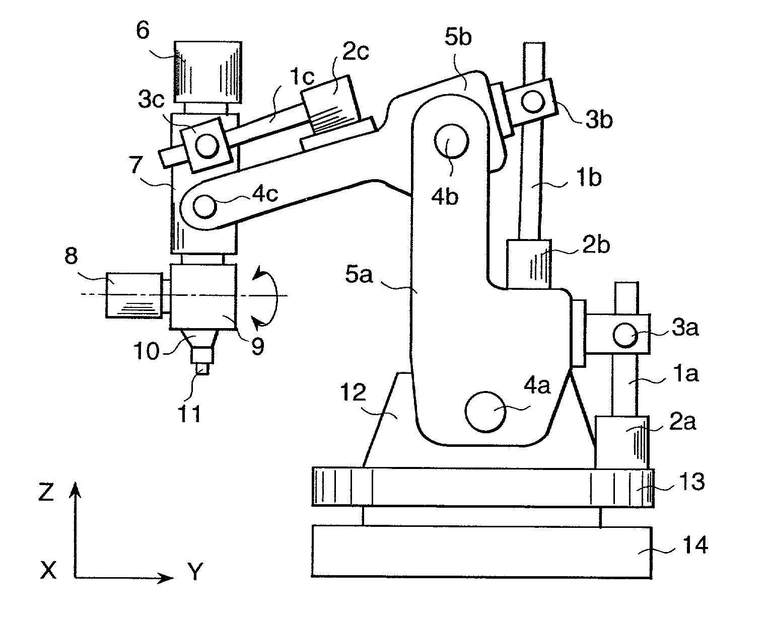
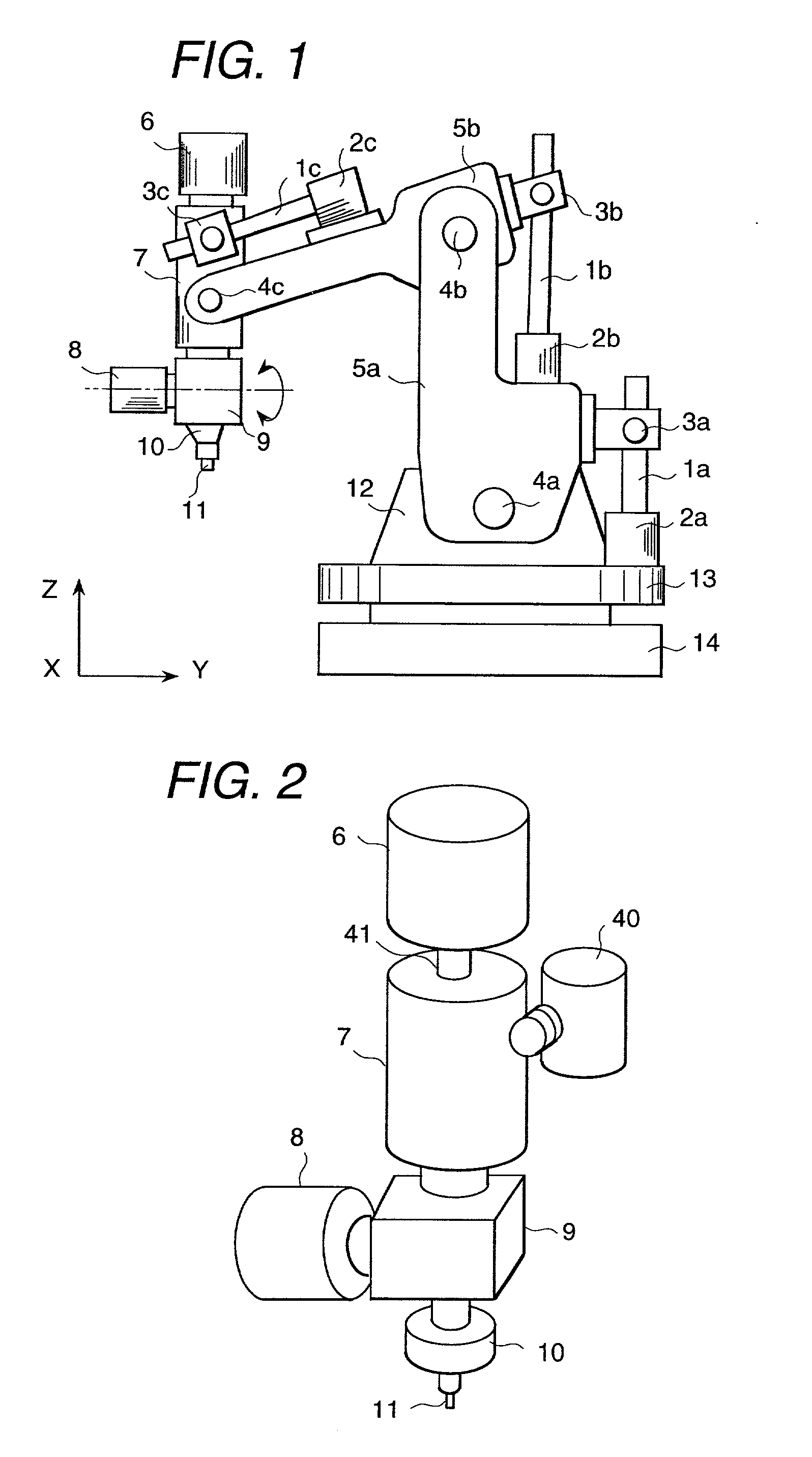
[0068] FIG. 1 is an entire block diagram showing an example of a friction stir welding apparatus according to the present invention. The numerals 1a, 1b and 1c denote ball screws, numerals 2a, 2b and 2c denote servo motors, numerals 3a, 3b and 3c denote bearings, numerals 4a, 4b and 4c denote link pins, numerals 5a and 5b denote second and first arms, respectively, numeral 6 denotes a main spindle rotating motor, numeral 7 denotes a pivoting member, numeral 8 denotes a bending drive member, numeral 9 denotes a rotational axis bending member, numeral 10 denotes a chucking member, numerals 11, 11a and 11b denote rotating tools, numeral 12 denotes a support base, numeral 13 denotes a rotary table, and numeral 14 denotes an apparatus base.

[0069] The second and first arms 5a, 5b are pivotable about the link pins 4a and 4b, respectively, as fulcrums. The main spindle rotating motor 6 and the rotating tool 11 are mounted to a distal end of the first arm 5b and can ...

second embodiment

[0077] (Second Embodiment)

[0078] FIG. 10 is an entire configuration diagram showing another example of a friction stir welding apparatus according to the present invention, in which the numeral 28 denotes a column, numeral 27 denotes an apparatus base, and numeral 26 denotes a workpiece mount.

[0079] In the same figure, the directions (X, Y, Z) indicated with both-end arrows are moving axis directions, which are orthogonal to one another. A main spindle rotating motor 6, pivoting member 7, bending drive member 8, rotational axis bending member 9, chucking member 10, and rotating tool 11 are mounted to a member adapted to move in Z-axis direction. All of these components move with motion of the Z axis.

[0080] With a driving force from a servo motor, the pivoting member 7 pivots about an axis parallel to the Z axis though not shown. The total pivoting angle is 370.degree. as is the case with the previous embodiment.

[0081] With the bending drive member 8, the direction of the rotational ...

third embodiment

[0088] (Third Embodiment)

[0089] FIG. 12 is a conceptual diagram showing a system configuration of a friction stir welding apparatus according to the present invention, in which the numeral 29 denotes a sensor, numeral 30 denotes the friction stir welding apparatus, numeral 31 denotes a workpiece, numeral 32 denotes an arithmetic unit, and numeral 33 denotes a control unit.

[0090] A coordinate value calculated from the shape of workpiece before the start of welding, a normal line direction of a joint region, and a tangential direction of a joint line are inputted as initial values to the control unit 33.

[0091] The friction stir welding apparatus 30 starts welding on the basis of the initial values. At the same time, the sensor 29 detects a positional relation between a rotating tool 11 and the workpieces 31 and inputs the result of the detection to the arithmetic unit 32. The arithmetic unit 32 collates the detection result with the initial values and inputs amendment values based on ...


PUM

PropertyMeasurementUnit
angleaaaaaaaaaa
attack angleaaaaaaaaaa
rotational angleaaaaaaaaaa

Abstract

It is an object of the present invention to provide a friction stir welding method and apparatus capable of maintaining a rotating tool and workpieces at a substantially constant geometrical relation for arbitrary curved surfaces having a three-dimensional shape, as well as a welded structure obtained thereby. The present invention resides in a friction stir welding method comprising joining workpieces while setting rotational angles of two rotational axes of a rotating tool which the two rotational axes are rotatable in intersecting directions or perpendicularly intersecting directions independently of rotation of the rotating tool, detecting a normal line direction with respect to joint surfaces of the workpieces and a tangential direction of a joint line, and joining the workpieces in three-dimensional directions while setting, on the basis of the detected normal line direction and tangential direction, an angle relative to a normal line direction, as well as a tangential direction, at a tip end of the rotating tool, and also resides in a friction stir welding apparatus using the said method.

Description

[0001] 1. Field of the Invention[0002] The present invention relates to a novel friction stir welding method and apparatus, as well as a welded structure obtained thereby. Particularly, the invention is concerned with a method and apparatus suitable for joining plural workpieces in a complicated three-dimensional shape.[0003] 2. Description of the Prior Art[0004] In Japanese Patent No. 2712838 (WO93 / 10935) is disclosed a friction stir welding method wherein a metallic rod (hereinafter referred to as "rotating tool"), which is substantially harder than the material of workpieces, is inserted into a joint region of the workpieces and is moved under rotation, and the workpieces are joined together with a frictional heat generated between the rotating tool and the workpieces. This friction stir welding method utilizes a plastic flow phenomenon induced with rotation of the rotating tool in which the workpieces are softened with a frictional heat developed between the workpieces and the r...

Claims


Application Information

Patent Timeline
Patent Type & Authority Applications(United States)
IPC IPC(8): B23K20/12B23K20/26
CPCB23K20/125B23K20/123B23K20/12
Inventor HIRANO, SATOSHIOKAMURA, HISANORIAONO, YASUHISAOKAMOTO, KAZUTAKAAOTA, KINYAODAKURA, TOMIOHASSHUU, SHINICHI
Owner HITACHI LTD
Why Eureka
Try Eureka