Friction Stir Welding Tool And Friction Stir Welding Method

a friction stir welding and stir welding technology, which is applied in the direction of manufacturing tools, soldering devices, auxillary welding devices, etc., can solve the problems of generating joining defects, workpiece movement and deformation, and considerable difficulty, so as to improve the service life of the probe, reduce the cost of the facility, and improve work efficiency

Inactive Publication Date: 2009-03-19
SHOWA DENKO KK +1
View PDF2 Cites 42 Cited by
  • Summary
  • Abstract
  • Description
  • Claims
  • Application Information

AI Technical Summary

Benefits of technology

[0028]When friction stir welding is performed by use of the friction stir welding tool according to par. 1), provisional friction stir welding is first performed, and main friction stir welding is then performed. The provisional friction stir welding is performed in such a manner that, while the rotor of the friction stir welding tool according to any one of pars. 1) to 8) is rotated, the projection for provisional joining is plunged into a joint interface between two workpieces such that the projection engages the two workpieces, and the two workpieces and the friction stir welding tool are moved relative to each other so as to intermittently weld the two workpieces along the joint interface by use of the projection for provisional joining. The main friction stir welding is performed in such a manner that, while the rotor of the friction stir welding tool is rotated, the probe is plunged into the joint interface such that the probe engages the two workpieces, and the two workpieces and the friction stir welding tool are moved relative to each other so as to continuously weld the two workpieces along the entire joint interface by use of the probe. Further, the projection for provisional joining is concentrically provided on the distal end surface of the probe of the friction stir welding tool, and a relation 0.3 D≦d≦0.8 D is satisfied, where D represents the diameter (mm) of the distal end surface of the probe, and d represents the diameter (mm) of the contour of the distal end surface of the projection for provisional joining. Therefore, the joining strength of each of joined portions formed by the provisional friction stir welding increases, and breakage of the joined portions during the subsequent main friction stir welding can be prevented. Accordingly, generation of joining defects, such as an internal defect of a joined portion and a form defect (e.g., misalignment) can be prevented. Further, the friction stir welding tool is not required to be exchanged with another friction stir welding tool having a different probe diameter between performance of the provisional friction stir welding and performance of the main friction stir welding. Therefore, work efficiency is improved. In addition, a plurality of friction stir welding tools are not required to be prepared, facility cost can be reduced.
[0029]According to the friction stir welding tool of par. 3), well-joined portions are obtained when the provisional friction stir welding is performed.
[0030]According to the friction stir welding tool of par. 5), the load which the probe receives from the workpieces during the main friction stir welding is reduced, whereby the service life of the probe is improved.
[0031]According to the friction stir welding tool of par. 7), the load acting on the projection for provisional joining when the projection for provisional joining is plunged into the workpieces is reduced, whereby the service lives of the projection for provisional joining and the probe are improved.
[0032]According to the friction stir welding tool of par. 8), the material stirring force during the provisional friction stir welding increases, whereby the speed of the provisional friction stir welding can be increased.
[0033]According to the friction stir welding method of par. 9), the joining strength of each of joined portions formed by the provisional friction stir welding increases, and breakage of the joined portions during the subsequent main friction stir welding can be prevented. Accordingly, generation of joining defects, such as an internal defect of a joined portion and a form defect (e.g., misalignment) can be prevented.

Problems solved by technology

Accordingly, the workpieces move and deform at the time of joining, possibly generating joining defects, such as an internal defect of a joined portion and a form defect (e.g., misalignment).
However, a considerable difficulty arises when a base having a circular recess and a circular cover fitted into the recess and closing the opening of the recess are joined together by friction stir welding.
However, in such a case, it is extremely difficult to carry out the friction stir welding over the entire joint interface in a state where the base and the cover are firmly fixed.
Therefore, the work of joining the cover to the base is troublesome.
Further, in the case where the cover is provisionally joined to the base at several points by a melt welding process, a blowhole, cracking, poor fusion, or a like defect is likely to arise.
This leads to an increase in the number of steps, thus impairing mass productivity.
Such probe exchange work is troublesome.
Therefore, the diameter ratio between the small diameter portion and the large diameter portion of the probe is not optimal for carrying out both the provisional friction stir welding and the main friction stir welding.

Method used


Image

  • Friction Stir Welding Tool And Friction Stir Welding Method
  • Friction Stir Welding Tool And Friction Stir Welding Method
  • Friction Stir Welding Tool And Friction Stir Welding Method

Examples


examples 1 to 3

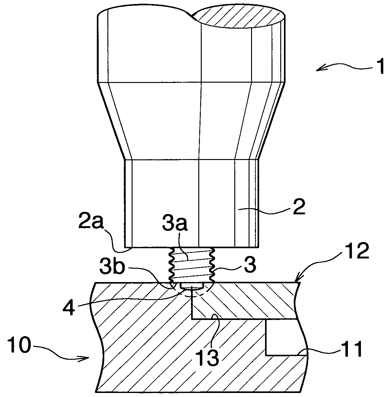
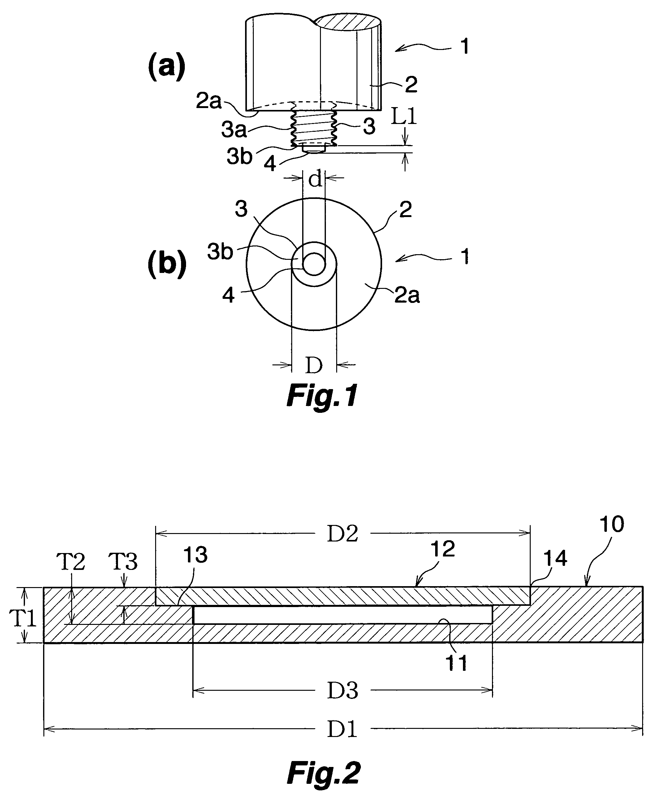
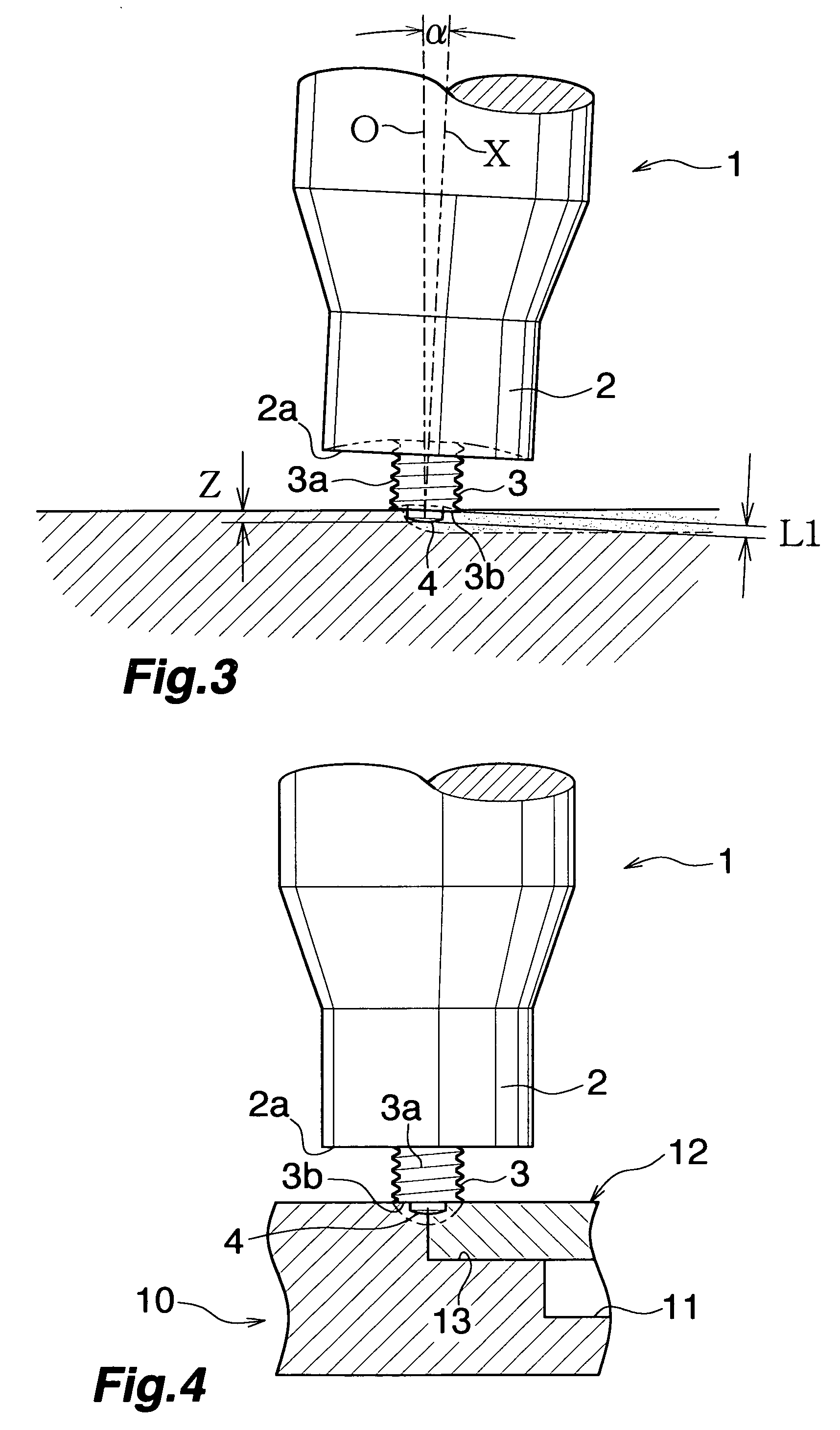
[0055]Three types of friction stir welding tools (1) were prepared. These friction stir welding tools (1) were formed such that the diameter of the shoulder portion (2a) of the distal end surface of the rotor (2): 18 mm; the diameter (D) of the distal end surface of the probe (3): 6 mm; the length (L2-L1) of the probe (3): 10 mm; the length (L1) of the provisional joining projection (4): 1 mm; the total length (L2) of the probe (3) and the provisional joining projection (4): 4.8 mm; and the diameter (d) of the contour of a transverse cross section of the provisional joining projection (4): 1.8 mm, 3 mm, and 4.8 mm, respectively.

[0056]Further, the base (10) and the cover (12) formed from JIS A6061-T6 were prepared. As shown in FIG. 2, the outside diameter (D1) of the base (10): 160 mm; thickness (T1) of the base (10): 15 mm; the total depth (T2) of the recess (11): 10 mm; the depth (T3) of the recess (2) as measured above the stepped portion (4): 5 mm; the diameter (D2) of the recess...


PUM

PropertyMeasurementUnit
lengthaaaaaaaaaa
lengthaaaaaaaaaa
lengthaaaaaaaaaa

Abstract

A friction stir welding tool 1 includes a rotor 2 to be attached to a rotation-drive section and a probe 3 concentrically provided on a distal end surface of the rotor 2. A provisional joining projection 4 is concentrically provided on a distal end surface of the probe 3. A relation 0.3 D≦d≦0.8 D is satisfied, where D represents a diameter (mm) of the distal end surface of the probe 3, and d represents a diameter (mm) of the contour of a transverse cross section of the provisional joining projection 4. The provisional joining projection 4 has a length of 0.3 to 2 mm. This friction stir welding tool can improve the work efficiency of friction stir welding and can carry out friction stir welding which is excellent in welding quality after main friction stir welding.

Description

TECHNICAL FIELD[0001]The present invention relates to a friction stir welding tool and a friction stir welding method.BACKGROUND ART[0002]In various industries such as the automobile industry, the shipbuilding industry, and the aerospace industry, the friction stir welding method, which is a solid-phase joining method, has been widely used, by virtue of its advantage that deformation or cracking caused by thermal strain is less likely to arise and the joining strength increases, as compared with the case of a melt welding process, such as TIG or MIG.[0003]Incidentally, the friction stir welding method uses a friction stir welding tool which includes a cylindrical columnar rotor attached to a rotation-drive section, and a probe concentrically provided on a distal end surface of the rotor. The probe is plunged into a joint interface between two workpieces while being rotated, and the probe and the two workpieces are caused to undergo relative movement. Therefore, friction heat and rel...

Claims


Application Information

Patent Timeline
Patent Type & Authority Applications(United States)
IPC IPC(8): B23K20/12
CPCB23K20/1255
Inventor NAGANO, YOSHITAKA
Owner SHOWA DENKO KK
Why Eureka
Try Eureka