

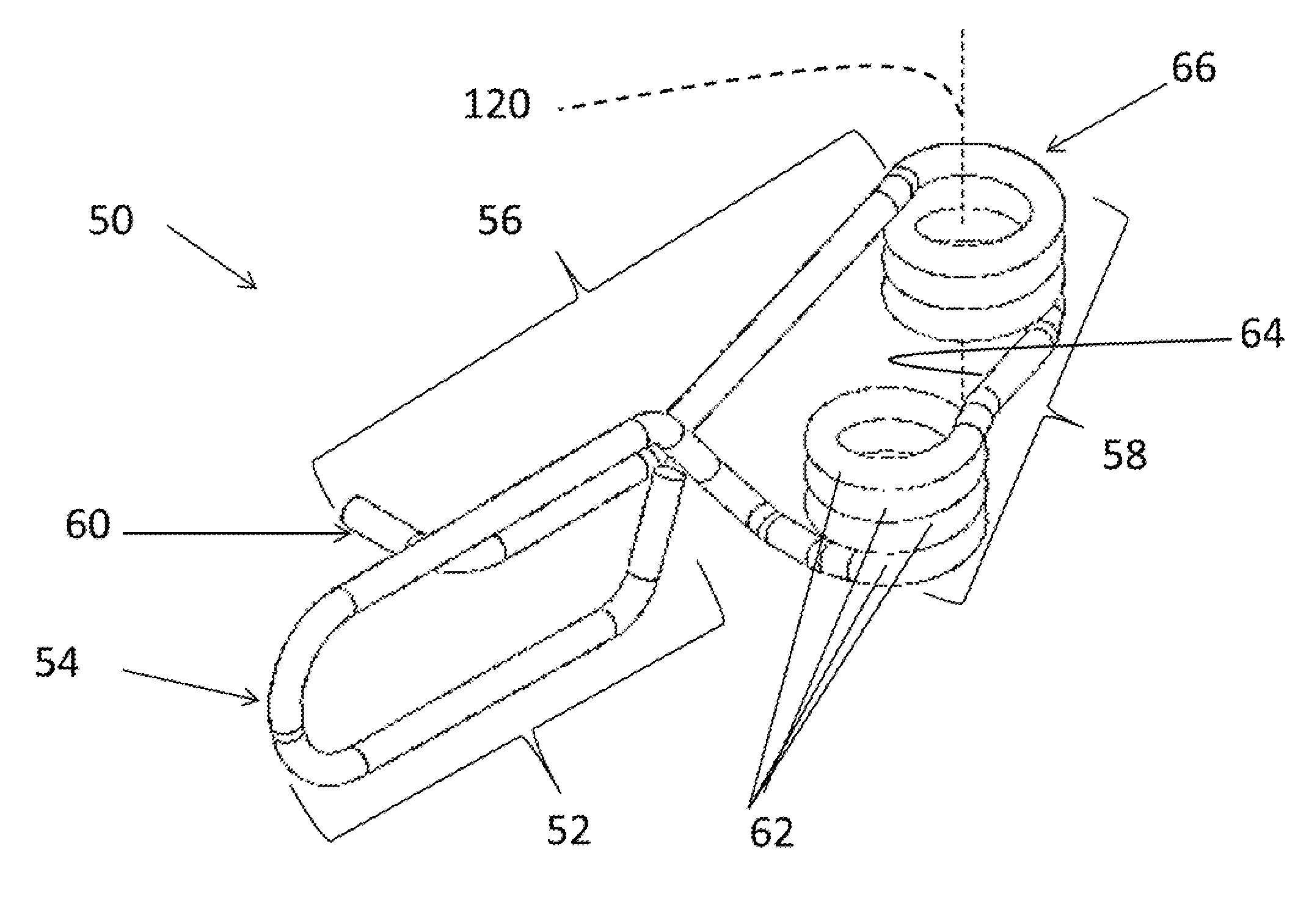
Coiled spreader spring
a spreader spring and coil technology, applied in the direction of axially engaging brakes, braking elements, brake types, etc., can solve the problems of affecting the performance of the spring, the spring may not be used with the existing braking system, and the other parts are damaged, so as to minimize and/or eliminate the movement, reduce noise, vibration, and harshness (nvh)/or eliminating the effect of reducing the movemen
- Summary
- Abstract
- Description
- Claims
- Application Information
AI Technical Summary
Benefits of technology
Problems solved by technology
Method used
Image

Examples
Embodiment Construction
[0026]The following description of the preferred embodiment(s) is merely exemplary in nature and is in no way intended to limit the invention, its application, or uses.
[0027]The present invention is predicated upon providing an improved spreader spring for use with a brake assembly in vehicles. For example, the spreader spring may be used with almost any brake assembly and the brake assembly may be used with almost any vehicle (e.g. car, truck, bus, train, airplane, or the like). Alternatively, the spreader spring and brake assembly may be integrated into components used for manufacturing or other equipment that require a brake such as a lathe, winder for paper products or cloth, amusement park rides, wind turbines, the like, or a combination thereof. However, the present invention is most suitable for use with a passenger vehicle (i.e. a car, truck, sports utility vehicle, or the like).
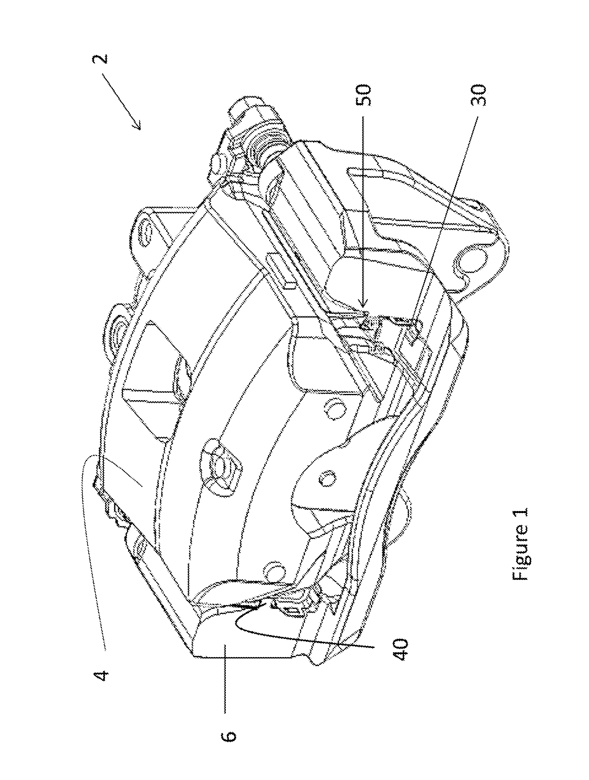
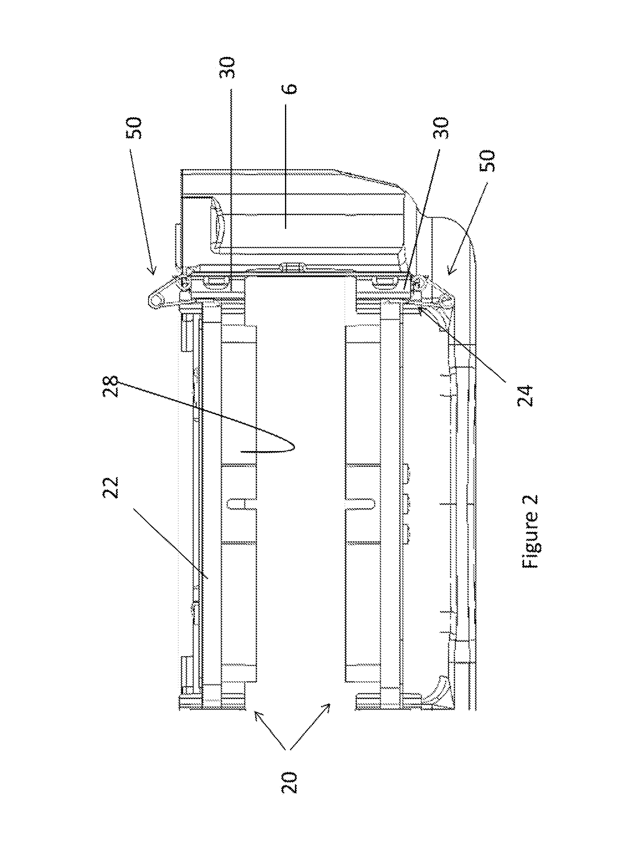
[0028]Generally, a disc brake assembly includes a caliper body, a rotor, and two brake pads. The ...
PUM
 Abstract
Description
Claims
Application Information