Electrical storage device thermal management systems

Active Publication Date: 2014-11-20
HAMILTON SUNDSTRAND CORP
View PDF8 Cites 56 Cited by
  • Summary
  • Abstract
  • Description
  • Claims
  • Application Information

AI Technical Summary

Benefits of technology

[0008]The subject invention is directed to a new and useful thermal management system such as for high density power sources. The system includes a housing with an interior divided by a bulkhead partition into first and second compartments. The first compartment is configured and adapted to house at least one electrical battery and the second compartment defines a coolant reservo

Problems solved by technology

However, some of these high energy chemistries are reported to have upper op

Method used


Image

  • Electrical storage device thermal management systems
  • Electrical storage device thermal management systems
  • Electrical storage device thermal management systems

Examples


Embodiment Construction

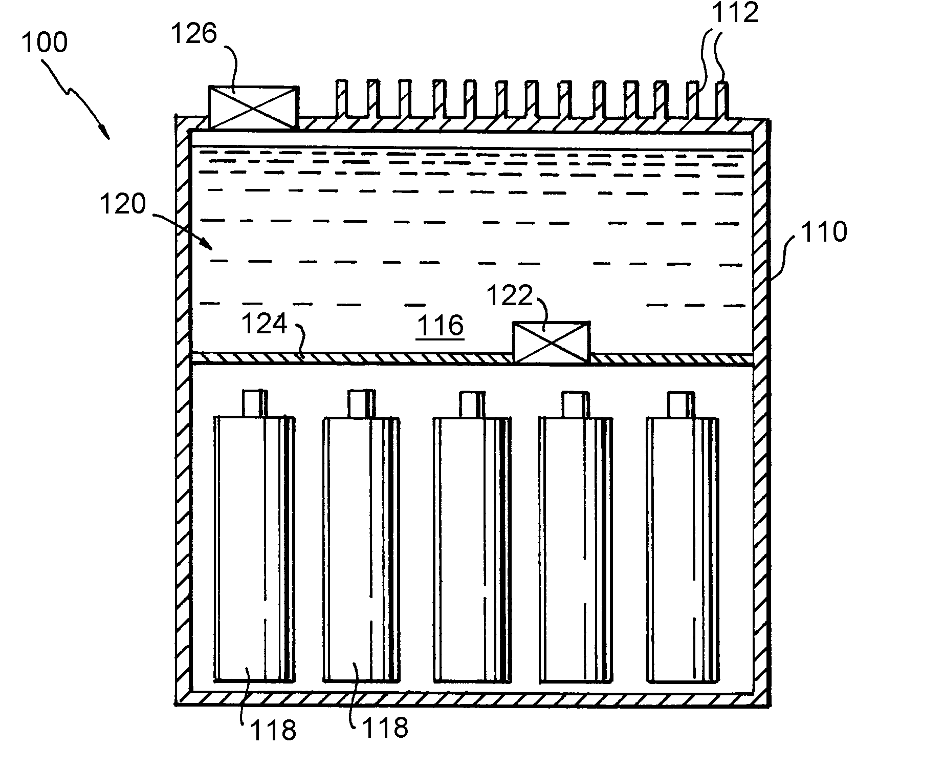
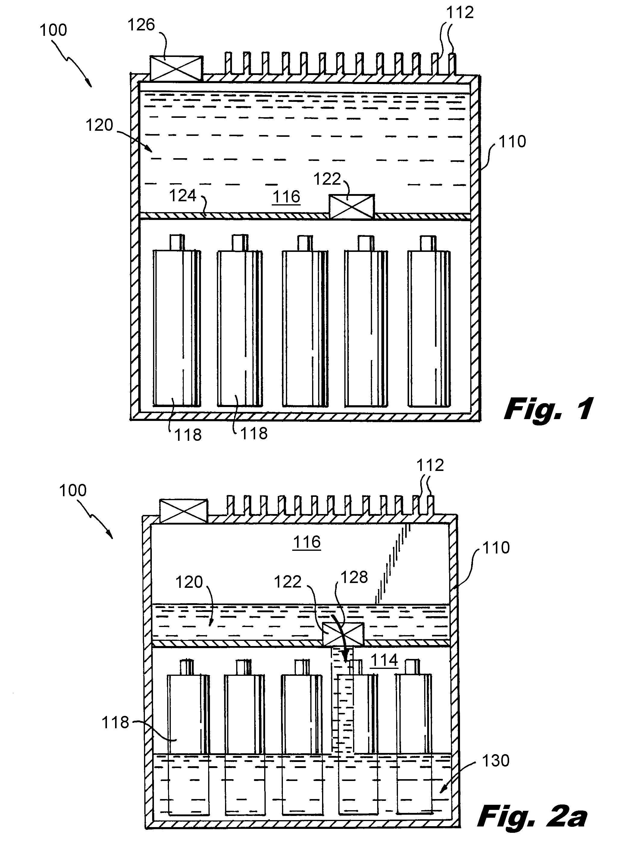
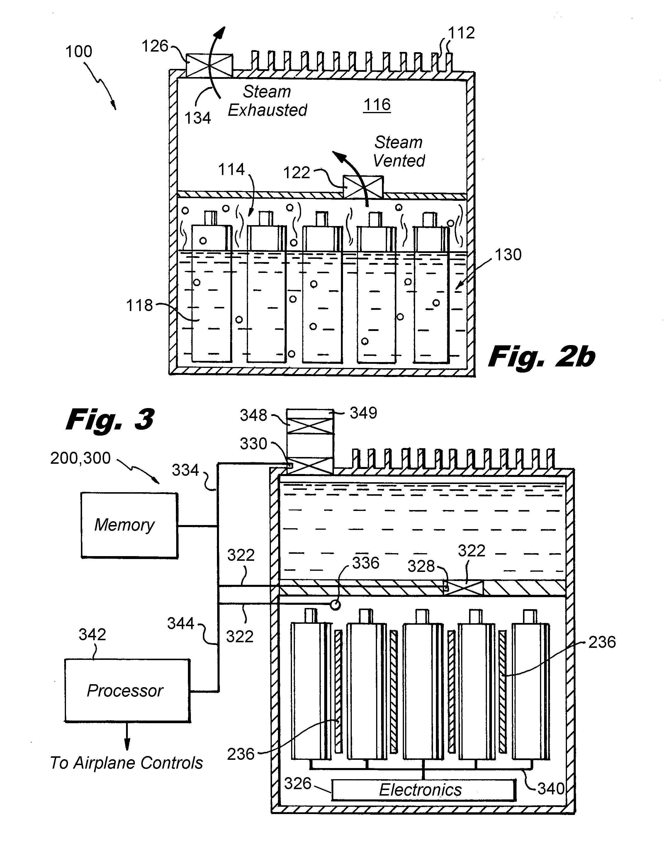
[0024]Reference will now be made to the drawings wherein like reference numerals identify similar structural features or aspects of the subject invention. For purposes of explanation and illustration, and not limitation, a partial view of an exemplary embodiment of a thermal management system in accordance with the invention is shown in FIG. 1 and designated with a reference numeral 100. Other embodiments of thermal management systems in accordance with the invention or aspects thereof are provided in FIGS. 2-4, as will be described. Applicant describes the power source herein as a battery. This is for illustrative purposes only and non-limiting. As will be appreciated, the power source can be any suitable source of electrical power such as conventional or high energy chemistry batteries as well as capacitors. The thermal management system of the invention can be used for management of vehicle power source temperature, and more specifically but without limitation thermal management ...


PUM


Abstract

A thermal management system for a high density power source is disclosed. The system includes a housing with an interior divided into first and second compartments. The first compartment is configured and adapted to house at least one electrical battery and the second compartment defines a coolant reservoir. A fluid release member connects the first and second compartments. Upon the first compartment reaching a temperature in excess of a predetermined limit, the fluid release member releases coolant form the second compartment into the first compartment to cool the at least one battery within the first compartment.

Description

BACKGROUND OF THE INVENTION[0001]1. Field of the Invention[0002]The present invention relates to thermal management systems for electrical storage devices, and more particularly to thermal management systems for batteries and capacitors used for power storage in aircraft.[0003]2. Description of Related Art[0004]Advances in electronics and electronics functionality have led to a proliferation of power consuming devices integrated into vehicles. Modern automobiles include numerous processors to manage vehicle systems previous controlled by mechanical systems. Modern aircraft include fly-by-wire systems connecting processors and actuators in placed of hydraulic systems because of the need for additional on-board functionality and weight savings. Increase in power demand gives rise to a corresponding requirement for electrical storage devices capable of meeting this increased power demand. Of particular interest are power sources with greater power density than conventional sources, the...

Claims


Application Information

Patent Timeline
IPC IPC(8): H01M10/66H01M10/6567H01M10/613H01M50/213H01M50/249
CPCH01M10/5093H01M10/5075H01M10/5004H01G2/08H01M2220/20H01M10/625H01M10/6551H01M10/6567H01M10/658H01G11/18H01G11/78H01M10/63H01M10/6569H01M10/643H01M10/6554H01M10/613Y02E60/10H01M50/3425H01M50/682H01M50/609H01M50/249H01M50/213Y02E60/13
Inventor ANDRES, MICHAEL J.
Owner HAMILTON SUNDSTRAND CORP
Why Eureka
Try Eureka