Imaging devices with light sources for reduced shadow, controllers and methods

a technology of controllers and light sources, applied in the direction of cameras, television systems, instruments, etc., can solve the problems of degrading image, wasting light source power at the start and end of each batch, and degrading range-finding, so as to reduce range-finding errors, improve image, and less error

Inactive Publication Date: 2014-11-27
SAMSUNG ELECTRONICS CO LTD
View PDF10 Cites 34 Cited by
  • Summary
  • Abstract
  • Description
  • Claims
  • Application Information

AI Technical Summary

Benefits of technology

[0025]Accordingly, any partial shadow or visible partial shadow can be reduced or eliminated completely, which both improves the image and reduces errors in range-finding. Moreover, range-finding is subject to fewer possible side reflections, and therefore subject to less error. As such embodiments of the invention remove errors in range-finding by preventing them from happening in the first place.
[0026]Additionally, the center portion of the imaged object does not become over-illuminated, and therefore pixels at the center of an imaging array have less chance of becoming saturated. Moreover, if implemented with rolling shutter operation, each light source will need to be turned on for a lesser time than otherwise, thus saving power. Further, embodiments are economical to implement, and increasingly important for 3D sensors, as resolution increases.

Problems solved by technology

The use of multiple such light sources, however, sometimes creates problems, both in the imaging function and in the range-finding function.
As such, areas VPS will appear as thin areas of shadows around edges of image of the front object, and thus degrade the image.
The above problem with imaging also degrades range-finding.
Due to the row exposure being staggered, some of the light source power is wasted at the start and end of each batch.
A problem in the prior art is, therefore, that the pixels at the center of the array become saturated more often.
The latter unwanted AC signal can be caused by lens blur and smear due to various internal optical reflections and imperfections in the camera and electrical imperfections of the sensor.
Both desired and undesired AC components will be sensed as sum of vectors by the pixel, thus causing accuracy degradation of measured distance, potentially making the pixel reading erroneous and potentially unusable, thus ultimately degrading camera's spatial resolution.
Since AC signal received from the foreground object is strong compared to AC signal received from the background object, even low degrees of blur and smear in the camera can cause the foreground AC signal to overpower the background AC signal, making pixel output unusable.
Range finding is also impacted by other sources of error.
FIG. 2 is a diagram showing how range finding by the imaging device of FIG. 1A can be subject to error due to reflections from a side object.
Here, multi-path illumination thus interferes with the regular illumination; at each pixel, electric fields are added by vector addition, causing error.
The presence of erroneous measurements can result in far-away objects appearing very close, thus likely preventing the application that is using range images from functioning correctly.

Method used


Image

  • Imaging devices with light sources for reduced shadow, controllers and methods
  • Imaging devices with light sources for reduced shadow, controllers and methods
  • Imaging devices with light sources for reduced shadow, controllers and methods

Examples


Embodiment Construction

[0043]As has been mentioned, the present description is about imaging devices, systems, controllers and methods. Embodiments are now described in more detail.

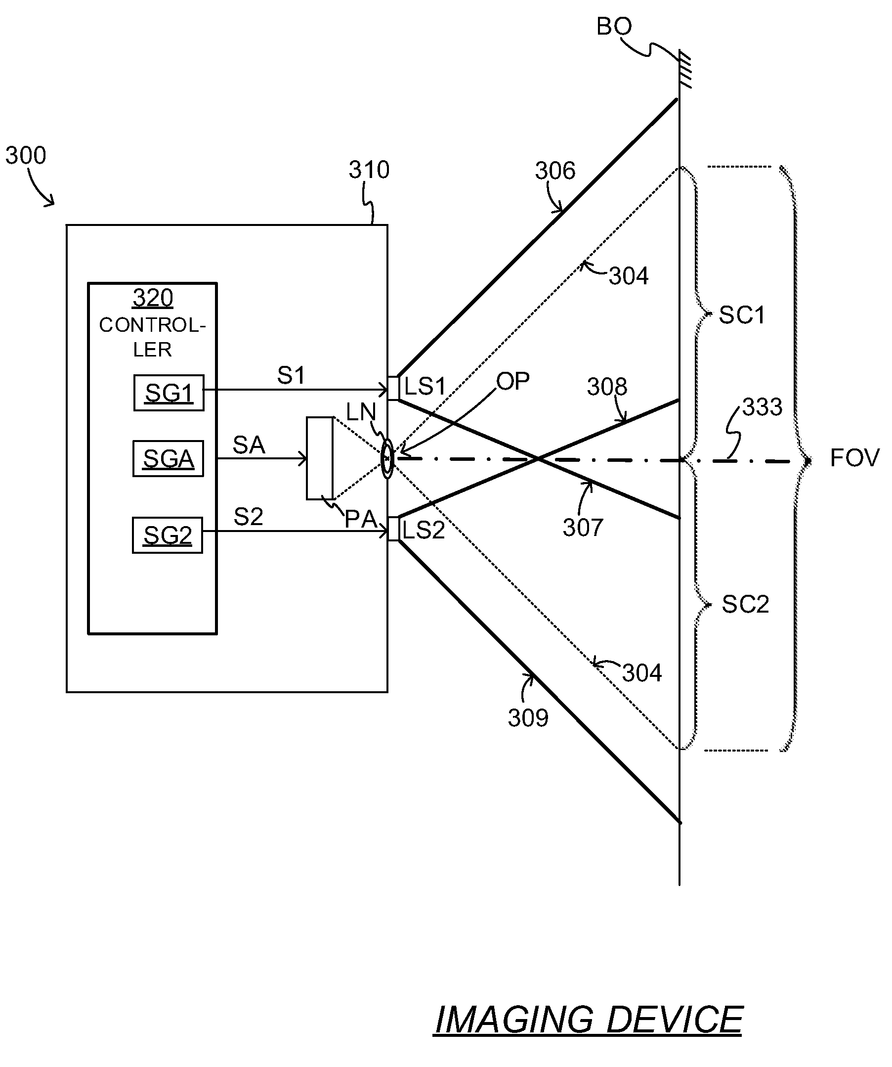
[0044]FIG. 3 is a block diagram of an imaging device 100 made according to embodiments. Imaging device 300 has a casing 310, and includes an opening OP in casing 310. An optional lens LN is provided at opening OP, although that is not necessary.

[0045]Device 300 also has a pixel array PA for receiving light through opening OP. Pixel array PA has rows and columns of pixels. Device 300 additionally includes a controller 320, for controlling the operation of pixel array PA and other components. Controller 320 is described in more detail later in this document. Imaging device 300 has a defined field of view (“FOV”) 304, which starts with opening OP and is bounded by rays also designated 304. Of course, the FOV is in three dimensions, while rays 304 are in the plane of the two-dimensional diagram.

[0046]Imaging device 300 also include...


PUM


Abstract

An imaging device includes a casing, a defined a field of view, and light sources on the casing. Each light source has a field of illumination configured to illuminate a respective distinct sector of the FOV at a higher intensity than the other sectors. Accordingly, any partial shadow or visible partial shadow around a front image can be reduced or eliminated completely.

Description

BACKGROUND[0001]Imaging devices, such as cameras, often use a light source, such as a flashlight, to illuminate their field of view. The object in the field of view receives the additional illumination, and reflects it back in the camera. The received reflection enables the imaging device with both functions of rendering an improved image of the object, and in more accurately determining the object's distance from the camera, which is also called range-finding.[0002]Multiple such light sources are sometimes used to increase the overall amount of illumination power. Sources used these days include light emitting diodes and laser diodes. The use of multiple such light sources, however, sometimes creates problems, both in the imaging function and in the range-finding function. A number of these problems are now described.[0003]FIG. 1A is a composite diagram that illustrates an imaging scenario. An imaging device 100 of the prior art, such as a camera, is shown in a plan view. Imaging d...

Claims


Application Information

Patent Timeline
Patent Type & Authority Applications(United States)
IPC IPC(8): H04N5/225G03B9/08
CPCG03B9/08H04N5/2256G03B2215/0564G03B15/05G03B2215/0503G03B2215/0571H04N23/56
Inventor OVSIANNIKOV, ILIAMIN, DONG-KI
Owner SAMSUNG ELECTRONICS CO LTD
Why Eureka
Try Eureka