Optical system for projection and projection-type display apparatus

a technology of optical system and display apparatus, which is applied in the direction of instruments, projectors, mountings, etc., can solve the problems of large apparatus size, and inability of optical system to cope with light valves, so as to prevent the achievement of high optical performance and reduce the size of the apparatus. , the effect of deterioration of optical performan

Active Publication Date: 2014-11-27
FUJIFILM CORP
View PDF4 Cites 13 Cited by
  • Summary
  • Abstract
  • Description
  • Claims
  • Application Information

AI Technical Summary

Benefits of technology

[0007]However, if a shift in a focal position caused by a change in temperature is corrected by selection of the material of lenses or by power balance, as in the technique disclosed in Patent Document 1, achievement of high optical performance may be prevented. Further, in the apparatus disclosed in Patent Document 2, the entire lens system is moved in the direction of the optical axis. Therefore, the size of the apparatus is large. In the technique disclosed in Patent Document 3, only a part of the optical system is moved. Therefore, the size does not become large. However, optical performance may deteriorate by correcting a shift in a focal position caused by a change in temperature, and the optical system may not be able to cope with a light valve with a higher definition of recent years.

Problems solved by technology

Therefore, the size of the apparatus is large.
However, optical performance may deteriorate by correcting a shift in a focal position caused by a change in temperature, and the optical system may not be able to cope with a light valve with a higher definition of recent years.

Method used


Image

  • Optical system for projection and projection-type display apparatus
  • Optical system for projection and projection-type display apparatus
  • Optical system for projection and projection-type display apparatus

Examples


example 1

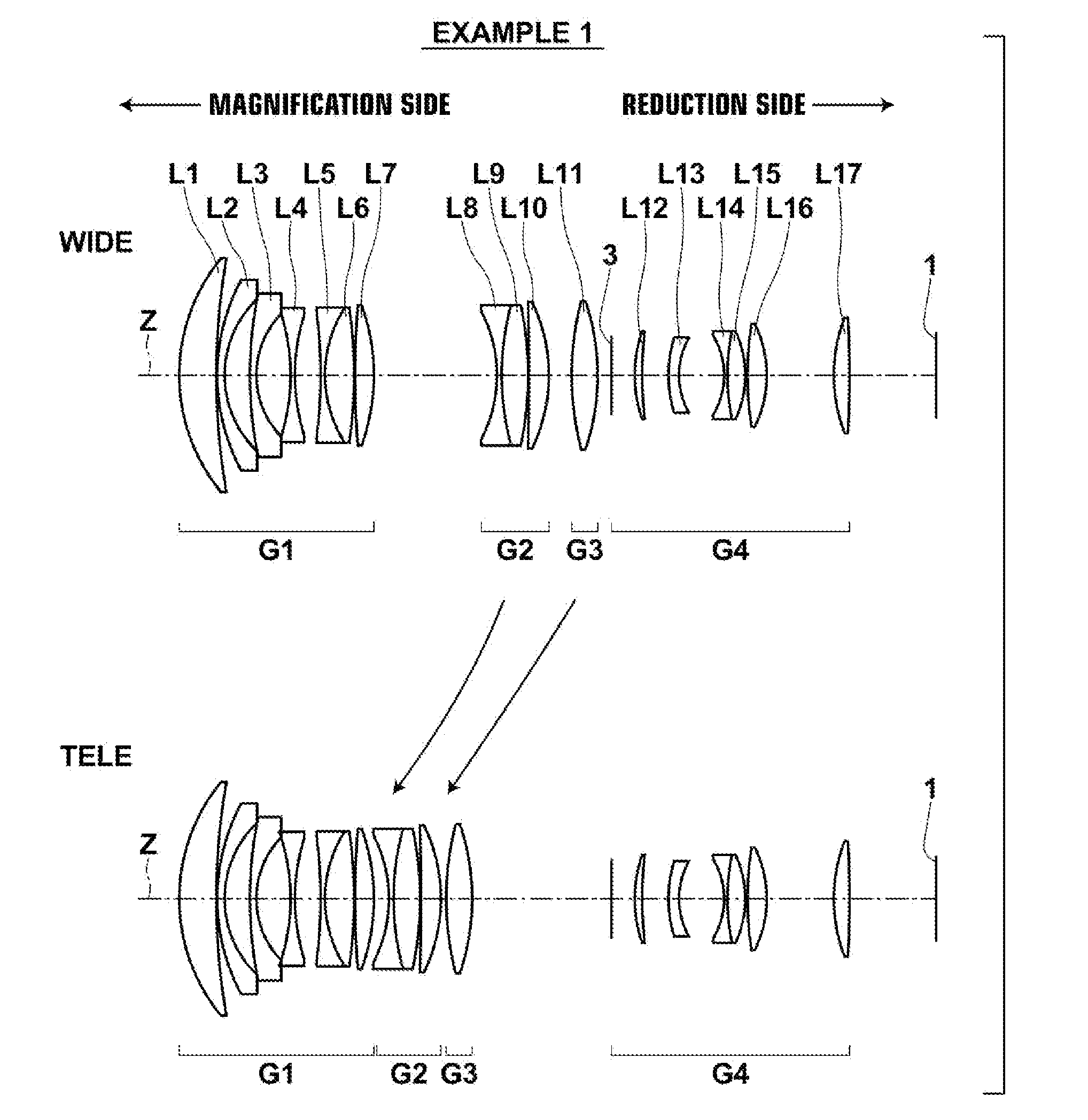
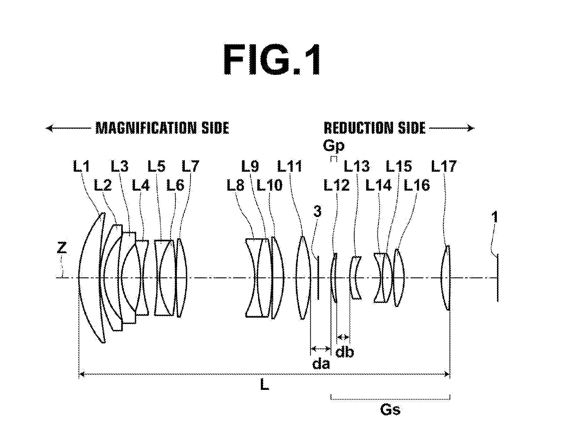
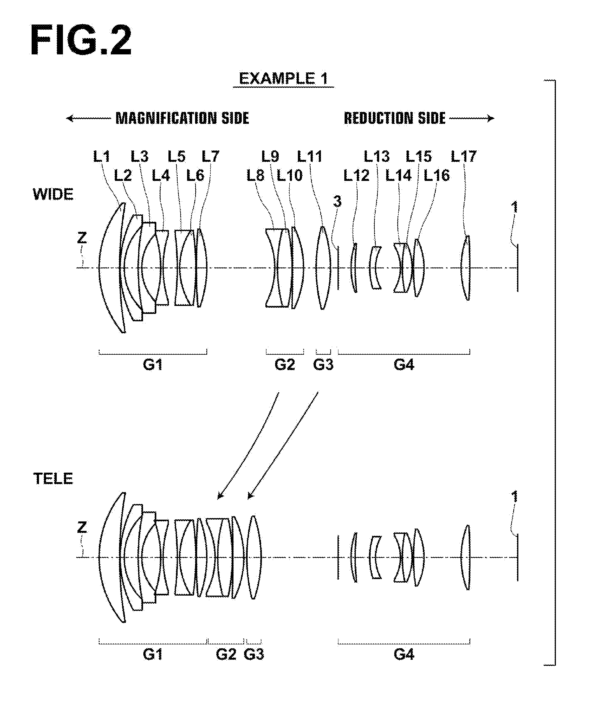
[0081]FIG. 2 is a diagram illustrating the lens structure of an optical system for projection in Example 1. The optical system for projection in Example 1 is a zoom lens substantially consisting of first lens group G1, second lens group G2, third lens group G3 and fourth lens group G4 arranged in this order from the magnification side. First lens group G1 and fourth lens group G4 are fixed during magnification change. The optical system is configured in such a manner that second lens group G2 and third lens group G3 move toward the magnification side while magnification is changed from a wide angle end to a telephoto end.

[0082]In FIG. 2, the upper row illustrates the arrangement of lenses at a wide angle end, and the lower row illustrates the arrangement of lenses at a telephoto end. Arrows between the upper row and the lower row schematically illustrate movement directions of lens groups that move during magnification change from a wide angle end to a telephoto end.

[0083]First lens...

example 2

[0091]FIG. 3 is a diagram illustrating the lens structure of an optical system for projection in Example 2. The optical system for projection in Example 2 is a zoom lens substantially consisting of first lens group G1, second lens group G2, third lens group G3 and fourth lens group G4 arranged in this order from the magnification side. First lens group G1 and fourth lens group G4 are fixed during magnification change. The optical system is configured in such a manner that second lens group G2 and third lens group G3 move toward the magnification side while magnification is changed from a wide angle end to a telephoto end.

[0092]First lens group G1 substantially consists of lens L1 through lens L7 arranged in this order from the magnification side. Second lens group G2 substantially consists of lens L8 and lens L9 arranged in this order from the magnification side. Third lens group G3 substantially consists of lens L10 and lens L11 arranged in this order from the magnification side. F...

example 3

[0095]FIG. 4 is a diagram illustrating the lens structure of an optical system for projection in Example 3. The optical system for projection in Example 3 is a zoom lens substantially consisting of first lens group G1, second lens group G2, third lens group G3, fourth lens group G4 and fifth lens group G5 arranged in this order from the magnification side. First lens group G1 and fifth lens group G5 are fixed during magnification change. The optical system is configured in such a manner that second lens group G2, third lens group G3 and fourth lens group G4 move toward the magnification side while magnification is changed from a wide angle end to a telephoto end. FIG. 4 illustrates an example in which a glass block 2 is arranged on the reduction side of fifth lens group G5. The glass block 2 is assumed to be a filter, a prism or the like used in a color combination unit or an illumination light separation unit.

[0096]First lens group G1 substantially consists of lens L1 through lens ...


PUM


Abstract

In an optical system for projection that is telecentric on a reduction side, a correction lens group substantially consisting of a part of lens groups in the optical system for projection is configured to move in the direction of an optical axis to correct a shift in a focal position caused by a change in temperature, and predetermined conditional formulas are satisfied.

Description

CROSS-REFERENCE TO RELATED APPLICATIONS[0001]This application is a Continuation of PCT International Application No. PCT / JP2013 / 000520 filed on Jan. 31, 2013, which claims priority under 35 U.S.C. §119 (a) to Japanese Patent Application No. 2012-025824 filed on Feb. 9, 2012. Each of the above applications is hereby expressly incorporated by reference, in its entirety, into the present application.BACKGROUND OF THE INVENTION[0002]1. Field of the Invention[0003]The present invention relates to an optical system for projection and a projection-type display apparatus. Particularly, the present invention relates to an optical system for projection that has taken temperature compensation into consideration and a projection-type display apparatus on which the optical system for projection is mounted.[0004]2. Description of the Related Art[0005]Conventionally, projection-type display apparatuses, which magnify and project an image displayed on a light valve, were used in presentation and th...

Claims


Application Information

Patent Timeline
Patent Type & Authority Applications(United States)
IPC IPC(8): G03B21/14G03B21/00G02B15/14G02B13/22G02B7/02
CPCG03B21/142G02B13/22G03B21/005G02B15/14G02B7/028G02B15/167G02B15/20G02B15/144G02B15/145
Inventor NAGATOSHI, YUKIKO
Owner FUJIFILM CORP
Why Eureka
Try Eureka