Luminal prosthesis and a gastrointestinal implant device

Active Publication Date: 2014-11-27
COLOPLAST AS
View PDF40 Cites 47 Cited by
  • Summary
  • Abstract
  • Description
  • Claims
  • Application Information

AI Technical Summary

Benefits of technology

[0021]In one embodiment the prosthesis has a reinforcement to facilitate radial compression during loading and to limit radial expansion. The reinforcement may extend around at least part of the circumference of the stent. The reinforcement may comprise at least one loop.
[0022]In one case the reinforcement is non-distensible. The reinforcement may be of flexible material. In one case the reinforcement is of a polymeric or metallic thread. The reinforcement may be a material selected from one or more of the group comprising monofilament or braided polypropylene suture or a stainless steel wire.
[0023]The inv

Problems solved by technology

Whilst many of these devices are successful in the short term various problems can ar

Method used


Image

  • Luminal prosthesis and a gastrointestinal implant device
  • Luminal prosthesis and a gastrointestinal implant device
  • Luminal prosthesis and a gastrointestinal implant device

Examples


Embodiment Construction

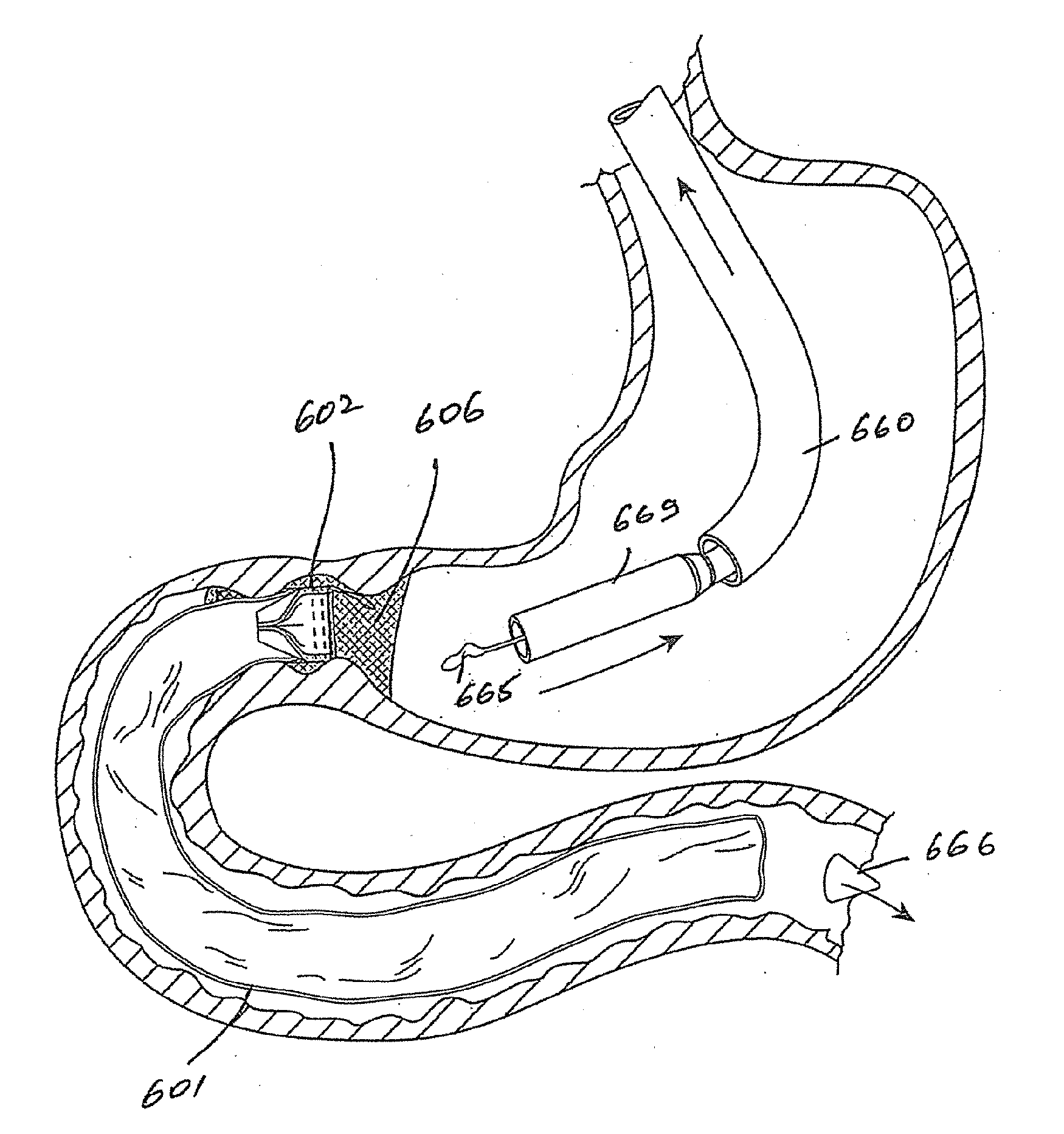
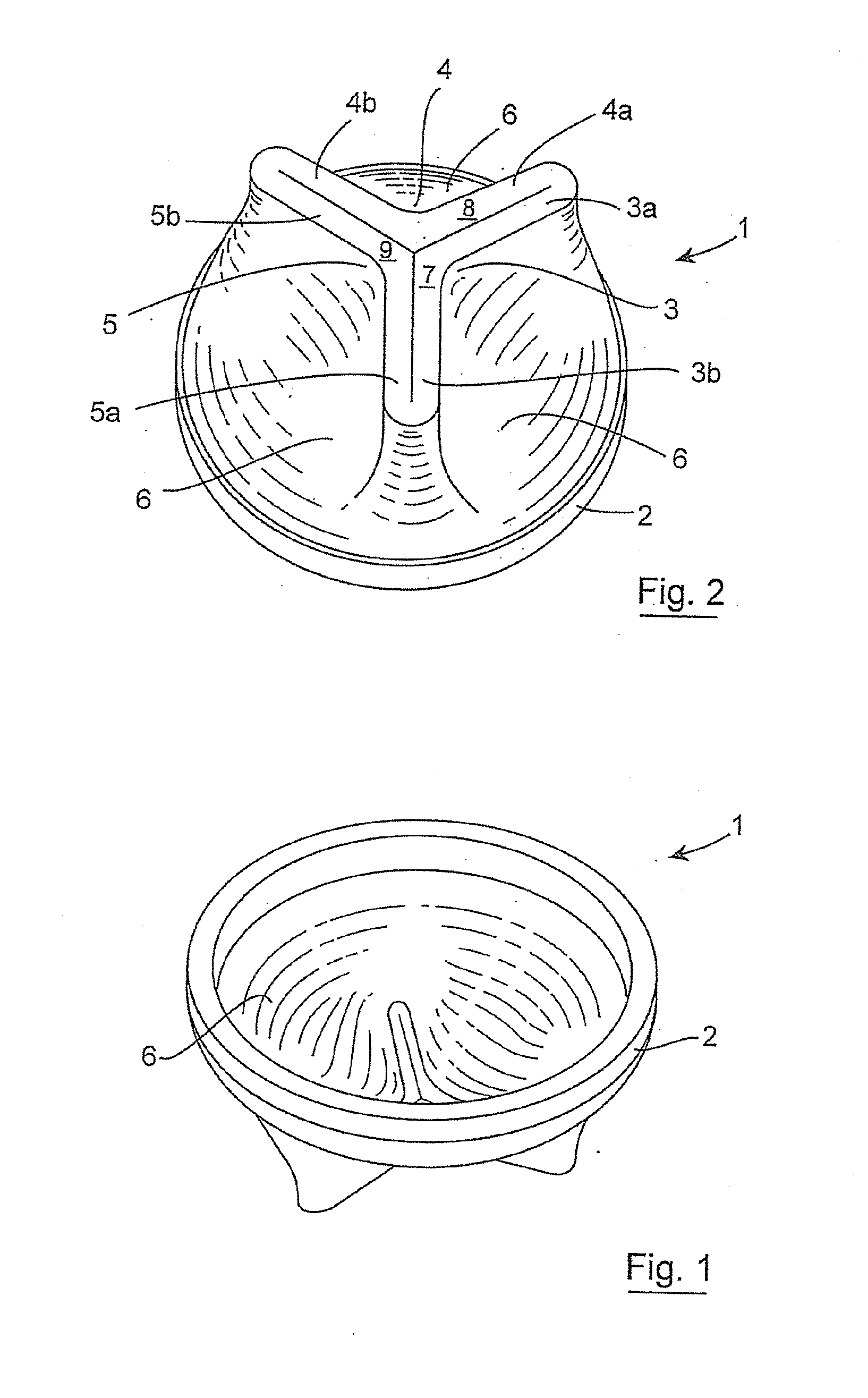
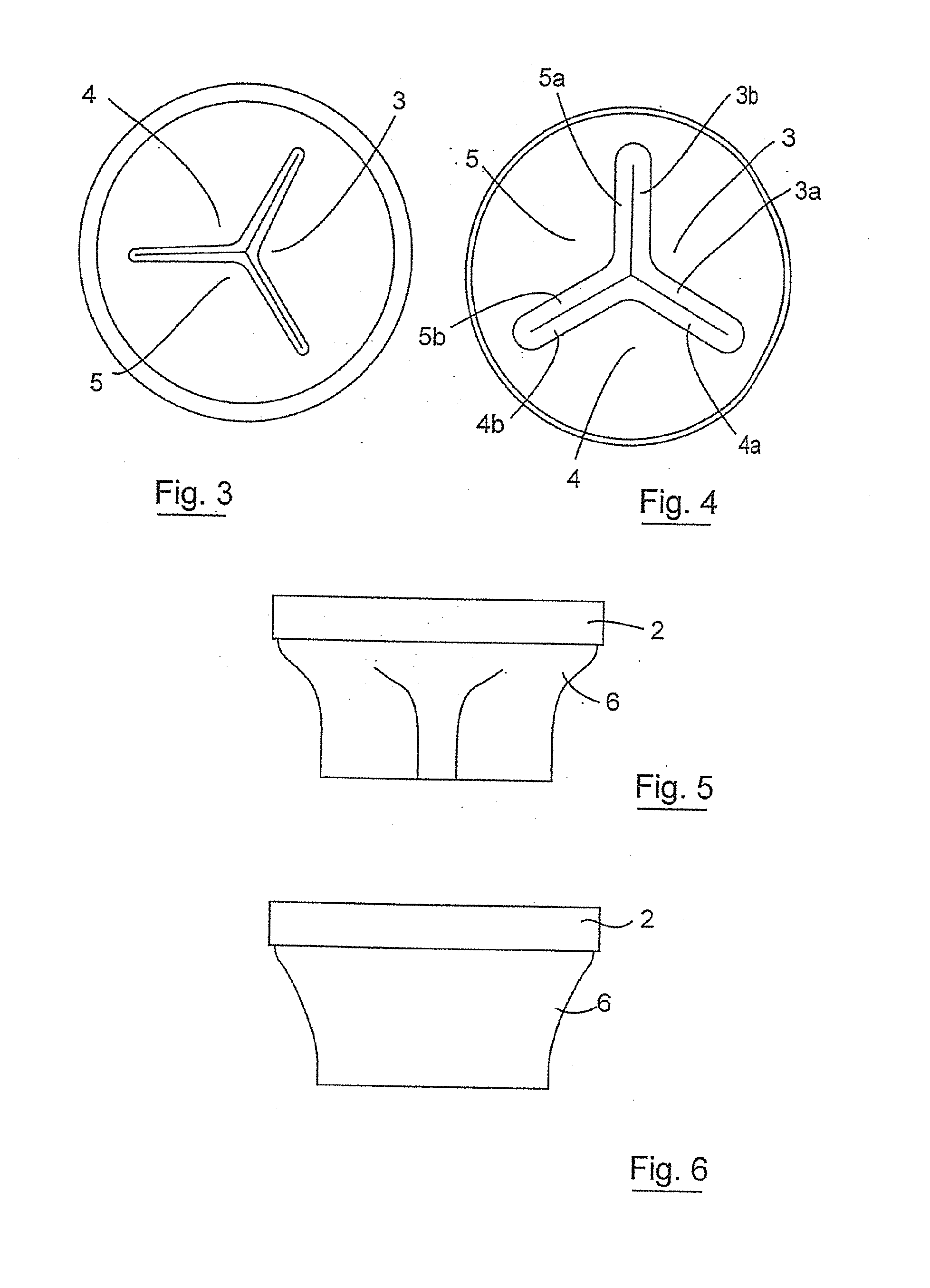
[0311]Referring to the drawings and initially to FIGS. 1 to 16 thereof there is illustrated a valve 1 which can open automatically in one direction.

[0312]The valve 1 comprises a polymeric valve body having a proximal outer support region with a rim 2, at least three valve leaflets 3, 4, 5, and a main body region 6 extending between the support rim 2 and the valve leaflets 3, 4, 5. The valve leaflets 3, 4, 5 extend inwardly and distally and terminate at distal end faces 7, 8, 9 respectively. The leaflets each 3, 4, 5 have legs a, b which extend at an included angle of 120° to each other. The adjacent pairs of legs 3a; 4a; 4b; 5b; 5a; 3b; co-apt to close the gap between the valve leaflets when the valve is in the normally closed configuration.

[0313]The valve 1 has two configurations. The first configuration is a normally closed configuration in which the valve leaflets 3, 4, 5 co-apt to close the valve. The second configuration is an open configuration in which the valve leaflets 3, 4...


PUM


Abstract

An inexpensive small-sized screen printing machine having low redundancy and high production efficiency and applicable to a dual conveying-type component mounting machine. A pair of substrate supporting tables juxtaposed in a specific direction is provided. Screen printing is alternately performed by a single print executing section in a common area which can be shared by the two substrate supporting tables. In doing so, when one substrate supporting table located at a print position among the pair of substrate supporting tables starts exiting the print position, the other substrate supporting table starts entry to the print position.

Description

INTRODUCTION[0001]The invention relates to a device. In one aspect the invention relates to a gastrointestinal implant device.[0002]There are several procedures and devices for treatment of obesity. Whilst many of these devices are successful in the short term various problems can arise because the patient does not achieve a feeling of satiety (fullness) after eating.STATEMENTS OF INVENTION[0003]According to the invention there is provided a luminal prosthesis comprising:[0004]a first part which is adapted to be retained in a lumen; and[0005]a second part which is connected to the first part such that a force applied to the second part is at least partially isolated from the first part.[0006]The second part may be adapted for mounting of a device such as a valve.[0007]The prosthesis may comprise a connector between the first part and the second part. The connector may comprise at least one tether. The connector may comprise at least one strut. The connector may comprise at least one...

Claims


Application Information

Patent Timeline
IPC IPC(8): A61F5/00A61F2/04
CPCA61F5/0079A61F2/04A61F2002/045A61F2220/0033A61F2220/0075A61F2/966A61F2002/044A61F2002/9511A61F2002/9528A61F2230/001A61F2/86
Inventor BEHAN, NIALL
Owner COLOPLAST AS
Why Eureka
Try Eureka