
Radar device and method of acquiring and tracking target

Inactive Publication Date: 2014-12-04
FURUNO ELECTRIC CO LTD
View PDF4 Cites 11 Cited by
  • Summary
  • Abstract
  • Description
  • Claims
  • Application Information

AI Technical Summary

Benefits of technology

The patent text describes a method for automatically identifying and tracking targets that need to be tracked, while excluding targets that do not require tracking. This results in a reduction of data processing requirements and a less burden on users and processors.

Problems solved by technology

Conducting this manual operation increases the user's burden.
Further, this radar signal processing device determines the possibility of a collision, and if there is the possibility of a collision, the device does not suspend the tracking even if the target is located within the area.
Therefore, the velocity vector, which is accurate, cannot be calculated for a while after the acquisition of the target.
Further, in JP2000-304853A, since processing which calculates a velocity vector of a target, using the specifying of the target by the user as a trigger, has been started, the necessity of the tracking of the target which exists around the ship cannot be determined.

Method used


Image

  • Radar device and method of acquiring and tracking target
  • Radar device and method of acquiring and tracking target
  • Radar device and method of acquiring and tracking target

Examples


Embodiment Construction

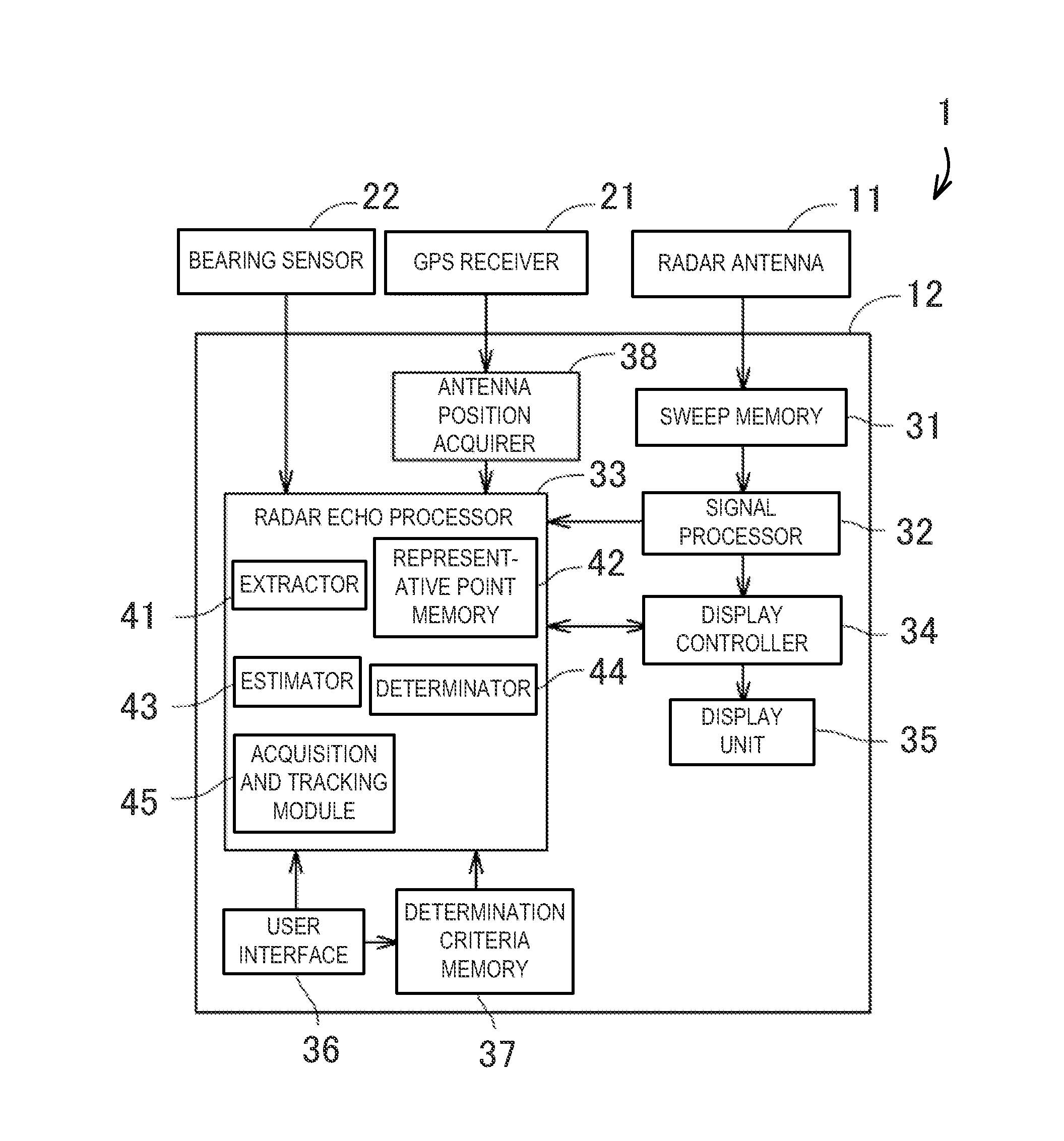
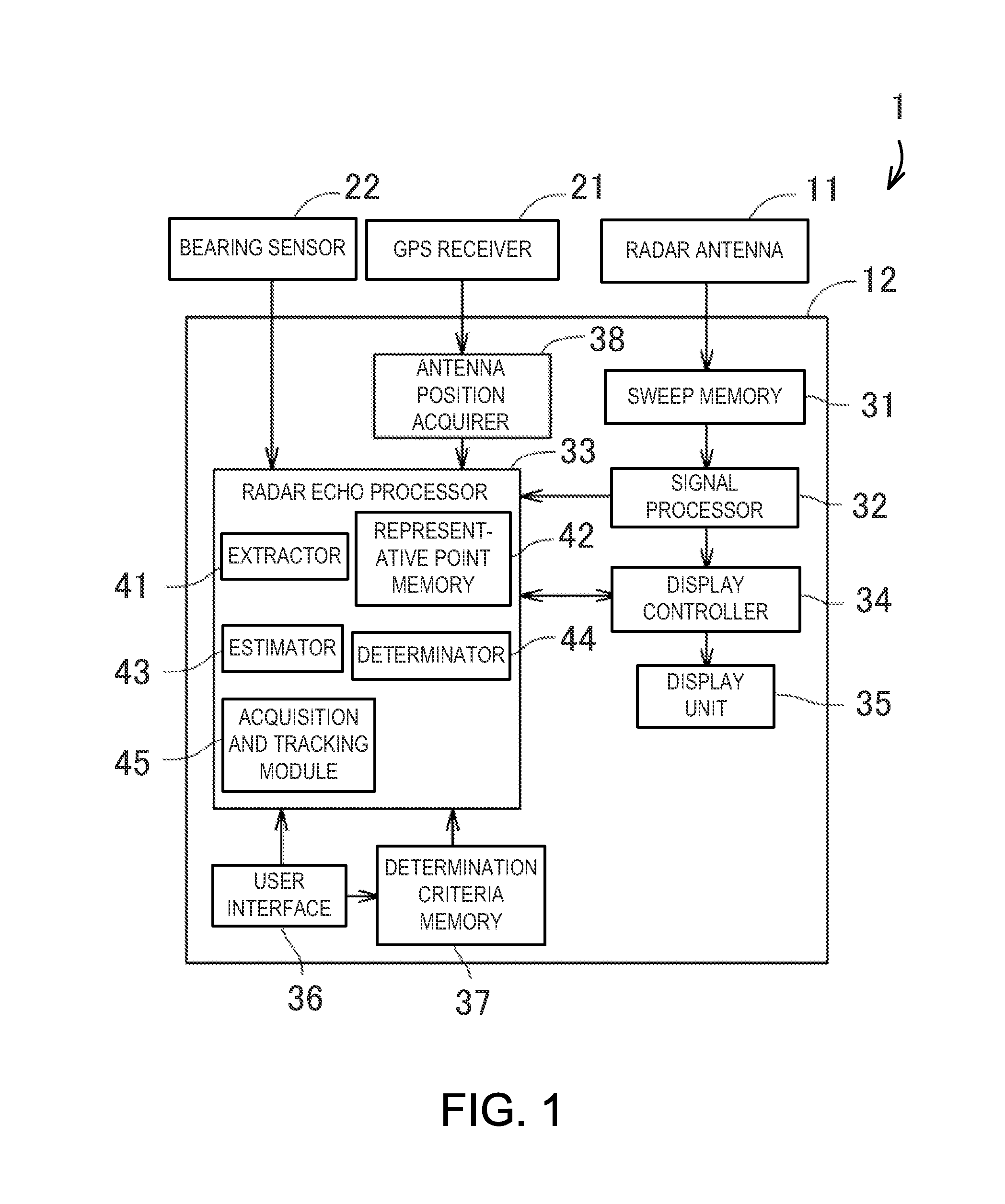
[0050]Next, one embodiment of the present invention is described with reference to the accompanying drawings.FIG. 1 is a block diagram of a radar device 1 according to one embodiment of the invention.

[0051]As illustrated in FIG. 1, the radar device 1 includes a radar antenna 11 and a radar indicator 12.

[0052]The radar device 1 is comprised of a pulse radar device in this embodiment. The radar antenna 11 transmits a pulse-shaped radio wave with a strong directivity, and then receives a reflected wave (radar echo) which is obtained by the pulse-shaped radio wave reflected and returned on / to a target. The radar antenna 11 repeats the transmission and the reception of the radio wave, while swiveling in a horizontal plane. Thus, the radar device 1 can scan along the horizontal plane throughout 360° centering on a ship which equips the radar device 1. The term “a ship which equips the radar device 1” as used herein is simply referred to as “the ship.” Further, the term “targets” as used h...


PUM


Abstract

A radar device is provided, which includes an extractor configured to extract a representative point of a target from a radar echo, a representative point memory configured to store the representative points extracted by the extractor, for a plurality of scans, an estimator configured to estimate movement information on the target indicated by the representative points based on the information stored in the representative point memory, a determinator configured to determine a possibility of a collision based on the movement information on the target estimated by the estimator, and an acquisition-and-tracking module configured to acquire and track the target determined to have the possibility of a collision by the determinator.

Description

CROSS-REFERENCE TO RELATED APPLICATION(S)[0001]The application claims priority under 35 U.S.C. §119 to Japanese Patent Application No. 2013-115566, which was filed on May 31, 2013, the entire disclosure of which is hereby incorporated by reference.TECHNICAL FIELD[0002]The present invention relates to a radar device, which primarily has a function to acquire and track a target.BACKGROUND OF THE INVENTION[0003]Conventionally, radar devices have been known, which have a “Target Tracking (TT)” function to track a target based on an echo signal received by a radar antenna. Here, the TT-function is, describing briefly, to detect a transition of the position of a target which exists around a ship, which equips the radar device (hereinafter, simply referred to as “the ship”), based on a transition of past radar images. By this TT-function, for example, a target with a possibility of a collision with the ship can be displayed along with a predetermined symbol.[0004]Acquisition of the target ...

Claims


Application Information

Patent Timeline
IPC IPC(8): G01S13/66G01S7/04G01S13/937
CPCG01S7/04G01S13/66G01S7/24G01S13/723G01S13/937
Inventor NOMURA, HIROYUKI
Owner FURUNO ELECTRIC CO LTD
Learn More