Water pump built-in comprehensive detection component and its usage method

A comprehensive detection and component technology, applied in pump control, measuring devices, non-variable pumps, etc., can solve problems such as large rotation resistance of submersible pump motor rotor, misjudgment of pump working status, inaccurate water level detection, etc., to achieve components The effect of reduction, simplicity of use, and concise structure

Active Publication Date: 2019-10-25
漯河市四通泵业有限公司
View PDF7 Cites 0 Cited by
  • Summary
  • Abstract
  • Description
  • Claims
  • Application Information

AI Technical Summary

Problems solved by technology

[0007] When it is detected at the same time that the water flow rate at the water inlet of the submersible pump is lower than the normal working water suction flow range of the submersible pump and the difference between the operating temperature of the driving motor of the submersible pump and the maximum operating temperature of the driving motor is less than 3-10°C, it means that the motor of the submersible pump is malfunctioning. The operating load is too large, and the rotor rotation resistance of the submersible pump motor is too large
[0008] This set is very cumbersome, the actual production cost increases, the sensor components, the failure rate is high, and the stability is low
Especially the water level detection uses a float and a connecting rod, and the device takes up a lot of space
In addition, the float and connecting rod are located outside the submersible pump. When used in the river, they are easily disturbed by the tank or other debris, resulting in inaccurate water level detection and misjudgment of the working status of the pump.

Method used


Image

  • Water pump built-in comprehensive detection component and its usage method
  • Water pump built-in comprehensive detection component and its usage method
  • Water pump built-in comprehensive detection component and its usage method

Examples


Embodiment Construction

[0037] The invention will be described in detail below in conjunction with the accompanying drawings.

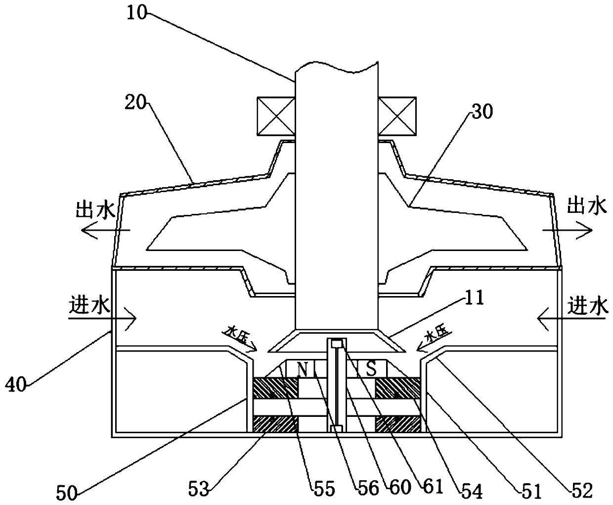
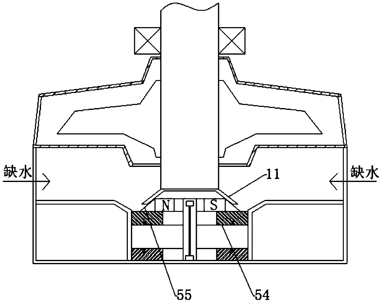
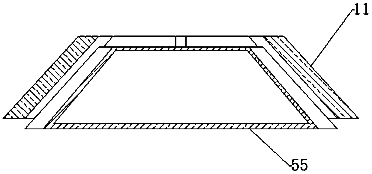
[0038] Such as Figure 1-3 As shown, a water pump control system includes a casing, a motor, and a water pump impeller 30 . The rotating shaft 10 of the motor is arranged vertically, and the water pump impeller 30 is set at the bottom. The bottom end of rotating shaft 10 stretches in the water inlet chamber 40, and a cone-shaped clutch ring 11 is fixed at its spare end.

[0039] A drainage ring 50 is fixed on the inner bottom of the water inlet chamber 40 . The drainage ring 50 includes a cylindrical barrel 51 , an inverted cone ring 52 and a plane ring. The cylindrical barrel 51 is coaxial with the rotating shaft 10 . The cylindrical tube 51 is coaxial with the inverted cone ring 52, and its top edge is sealed and fixed with the bottom edge of the inverted cone ring 52. The face seal is fixed.

[0040] A ring magnet 53 is fixed at the inner bottom of the cylindrical bar...


PUM


Abstract

The invention discloses a water pump built-in comprehensive detection assembly and an using method thereof. The water pump built-in comprehensive detection assembly comprises a machine shell, a motorand a water pump impeller; a rotating shaft of the motor is vertically arranged, the bottom of the rotating shaft is sleeved with the water pump impeller, the water pump impeller is located in a wateroutlet cavity, the lower side of the water outlet cavity is a water inlet cavity, the bottom end of the rotating shaft extends into the water inlet cavity, and a conical annular clutch ring is fixedat a spare end of the rotating shaft; a drainage ring is fixed on the inner bottom surface of the water inlet cavity, the inner bottom surface of the water inlet cavity further comprises an annular magnet, the magnetic poles of the annular magnet are distributed in the axial direction, a second annular magnet is placed at the position, above the annular magnet, in a cylindrical barrel, wherein themagnetic poles of the second annular magnet are opposite to the magnetic poles of the annular magnet, and the annular magnet repels to the second annular magnet all the time; the top surface of the second annular magnet is fixedly provided with a conical annular type abutting box, a third magnet is fixed in the abutting box; and the bottom of the cylindrical barrel is further fixedly provided with a sensing coil assembly, and further comprises a temperature sensing assembly. When the third magnet rotates, the sensing coils are driven to passively cut magnetic induction lines to form a current, so that the water level and the flow can be monitored, and the inner temperature of the motor can be detected through the temperature sensing assembly.

Description

technical field [0001] The invention relates to a water level and flow detection assembly used in a control system of a submersible pump. Background technique [0002] The submersible pump is an important equipment used to transmit the water source of the water source to a longer distance or to a higher position. It is widely used in many life and production fields such as groundwater mining, mine operations, and landscape fountains. Because the submersible pump When running, it needs to be soaked in water, so its driving motors are in a completely sealed state, which makes it unable to dissipate heat through air during operation, but completely relies on water flow for heat dissipation. It will cause the motor to burn out, which will cause the submersible pump to fail. At the same time, because the working position of the submersible pump is in the water, it is very inconvenient to maintain. In order to solve this problem, the current common method is to add a water level s...

Claims


Application Information

Patent Timeline
Patent Type & Authority Patents(China)
IPC IPC(8): F04D15/00G01D21/02
CPCF04D15/00G01D21/02
Inventor 周向阳
Owner 漯河市四通泵业有限公司
Why Eureka
Try Eureka