Membrane-electrode assembly, direct carbon fuel cell including the same, and method of preparing the same

a technology of direct carbon fuel cell and membrane electrode, which is applied in the direction of cell components, final product manufacturing, sustainable manufacturing/processing, etc., can solve the problems of current collecting methods used in a conventional solid oxide fuel cell (sofc) that cannot be employed in the same way to and the difficulty of reaction between solid carbon and a solid anode catalyst, etc., to achieve the effect of improving the resulting performance of a direct carbon fuel cell and reducing the electron transfer resistan

Active Publication Date: 2014-12-04
GWANGJU INST OF SCI & TECH
View PDF0 Cites 2 Cited by
  • Summary
  • Abstract
  • Description
  • Claims
  • Application Information

AI Technical Summary

Benefits of technology

The technical effect of this patent is to offer a way to charge solid carbon fuels that reduces the obstacles when it comes to electronic movement and fuel flow at the surface, leading to improved functioning of direct carbon fuel cells.

Problems solved by technology

The technical problem addressed in this patent is the difficulty of making reaction occur between solid carbon and a solid anode catalyst at a three-phase boundary in contact with a porous catalyst in a direct carbon fuel cell. Existing methods to improve the reactivity at the anode electrochemical reaction interface compromise thermodynamic advantages that produce at least 80% efficiency in a direct electrochemical reaction. The challenge is to reduce the ohmic resistance between the membrane-electrode assembly and the current collector, as well as to charge the solid carbon fuel efficiently, while also improving the reactivity at the anode electrochemical reaction interface.

Method used


Image

  • Membrane-electrode assembly, direct carbon fuel cell including the same, and method of preparing the same
  • Membrane-electrode assembly, direct carbon fuel cell including the same, and method of preparing the same
  • Membrane-electrode assembly, direct carbon fuel cell including the same, and method of preparing the same

Examples


example

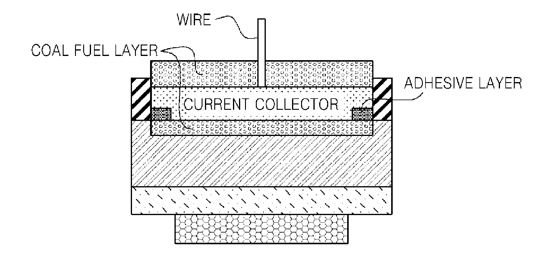
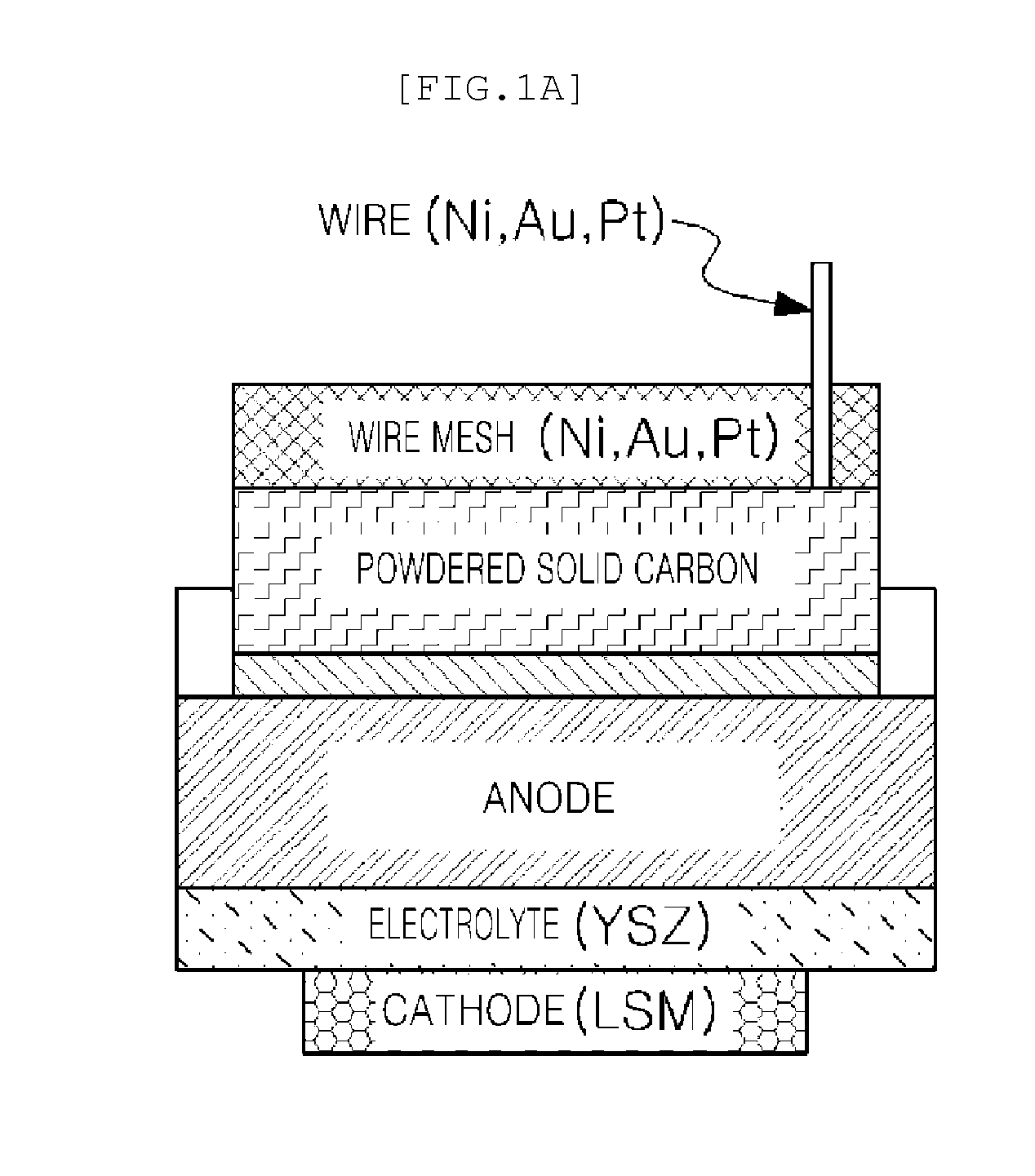
[0046]0.5 g of coal and 0.2 mL of ethylene glycol were mixed to produce gel type fuel, and loaded into anode. Then, thus prepared cell was connected with Pt wire in the reactor body. Prior to temperature rising of DCFC, Ar gas was injected thereinto for at least 30 minutes for ventilation so as to remove any oxygen remaining in the reaction site of the anode, and then selectively discharge gas in a manner of downward substitution at the end of the vent of the anode. Temperature was elevated at 5° C. / min through furnace. Constant flow rate of inert gas (Ar) was injected consecutively into the anode, and constant flow rate of air or oxygen was injected into the cathode. In the examples of the present invention, we operated the reactor at the interval of 50° C. in the temperature range of from 750° C. to 900° C., and conducted experimentation after stabilizing period of at least several minutes.

[0047]As set forth above, according to exemplary embodiments of the present invention, elect...


PUM


Abstract

Disclosed herein is a direct carbon fuel cell in which a coal fuel is oxidized electrochemically so as to create electrons to cause the electrons to generate electricity by a voltage difference between two electrodes. Specifically, a membrane-electrode assembly for operating a low rank coal fuel, a direct carbon fuel cell including the same, and a method of preparing the same are provided.

Description


Claims


Application Information

Patent Timeline
Owner GWANGJU INST OF SCI & TECH
Why Eureka
Try Eureka