Heating Element for Reducing Foaming During Saliva Collection

a heating element and saliva collection technology, applied in medical science, other nursing devices, other medical devices, etc., can solve the problems of simple barrier itself being fouled, risking saliva reaching the vacuum pump or other vacuum source, and operation of the vacuum system, so as to reduce or eliminate the formation

Inactive Publication Date: 2014-12-11
APNICURE
View PDF10 Cites 3 Cited by
  • Summary
  • Abstract
  • Description
  • Claims
  • Application Information

AI Technical Summary

Benefits of technology

[0011]The present disclosure provides apparatus and methods for the improved collection of saliva from aspirated air streams entrained with saliva, typically originating from a patient's oral cavity. In particular, the present disclosure provides for collecting saliva with reduced or eliminated formation of bubbles and foam in a collection reservoir. As described above, use of a vacuum to aspirate air from a patient's oral cavity can result in entrained saliva which should be removed before the aspirated air stream reaches a vacuum pump or other vacuum source. While a simple collection reservoir may be placed in a vacuum line from the oral cavity before the pump, as described in U.S. Patent Publication No. 2012 / 0132216, where the majority of saliva will drop to the bottom of the collection reservoir, excessive bubbles and foaming can result in loss of saliva through an outlet port on the reservoir, thus risking saliva reaching the vacuum pump or other vacuum source.
[0014]The present disclosure also provides for further improvement in saliva collection reservoirs and methods by providing an antechamber along an air flow path from the oral device to the vacuum or other source. In particular, air aspirated from the oral cavity of a patient passes through the antechamber before entering the interior volume of the reservoir. The geometry of the antechamber is configured to encourage bubble popping. The shape of the antechamber and its multiple openings to the interior volume of the reservoir stress the bubbles in a non-uniform way and encourages the breakage of the bubbles. The saliva resulting from the suppression and breakage of bubbles and foam drains from the antechamber to be collected at the bottom of the reservoir.
[0017]In the exemplary embodiments, the bubble barrier will be a cylindrical mesh or perforated wall which is arranged axially within the reservoir to define an outer annular region for receiving the airflow from the patient's oral cavity and an inner region which allows fluid collection and flow of the pre-treated air from which the bubbles and foam have been removed. The use of such a vertical, cylindrical barrier can be advantageous since it can maximizes the area available to disrupt the foam and bubbles and is least affected by a rising level of the saliva as it drains and collects on the bottom of the reservoir.
[0021]Exemplary embodiments of the present disclosure will further comprise inlet and outlet valves at the inlet and outlet of the reservoir, respectively. The valves will typically be self-opening valves which open when a line or fitting are connected to the reservoir for use and which close when the line or fitting is removed. In this way, the reservoir can be conveniently removed from the system while minimizing the risk that the collected saliva will be unintentionally spilled.

Problems solved by technology

While a simple collection reservoir may be placed in a vacuum line from the oral cavity before the pump, as described in U.S. Patent Publication No. 2012 / 0132216, where the majority of saliva will drop to the bottom of the collection reservoir, excessive bubbles and foaming can result in loss of saliva through an outlet port on the reservoir, thus risking saliva reaching the vacuum pump or other vacuum source.
While the passage of saliva bubbles and foam through the outlet port might be overcome by a simple membrane or other barrier placed over the outlet port, it has been found by the inventors herein that such a simple barrier can itself become fouled over time which can interfere with operation of the vacuum system.
Thus, even if saliva is inhibited from leaking from the reservoir, operation of the vacuum system may still be impaired.
The shape of the antechamber and its multiple openings to the interior volume of the reservoir stress the bubbles in a non-uniform way and encourages the breakage of the bubbles.
The heating element disrupts bubbles and foam present in the air stream such that the disrupted bubbles and foam evaporate or drain into the interior volume of the reservoir as liquid saliva or some combination of both.

Method used


Image

  • Heating Element for Reducing Foaming During Saliva Collection
  • Heating Element for Reducing Foaming During Saliva Collection
  • Heating Element for Reducing Foaming During Saliva Collection

Examples


Embodiment Construction

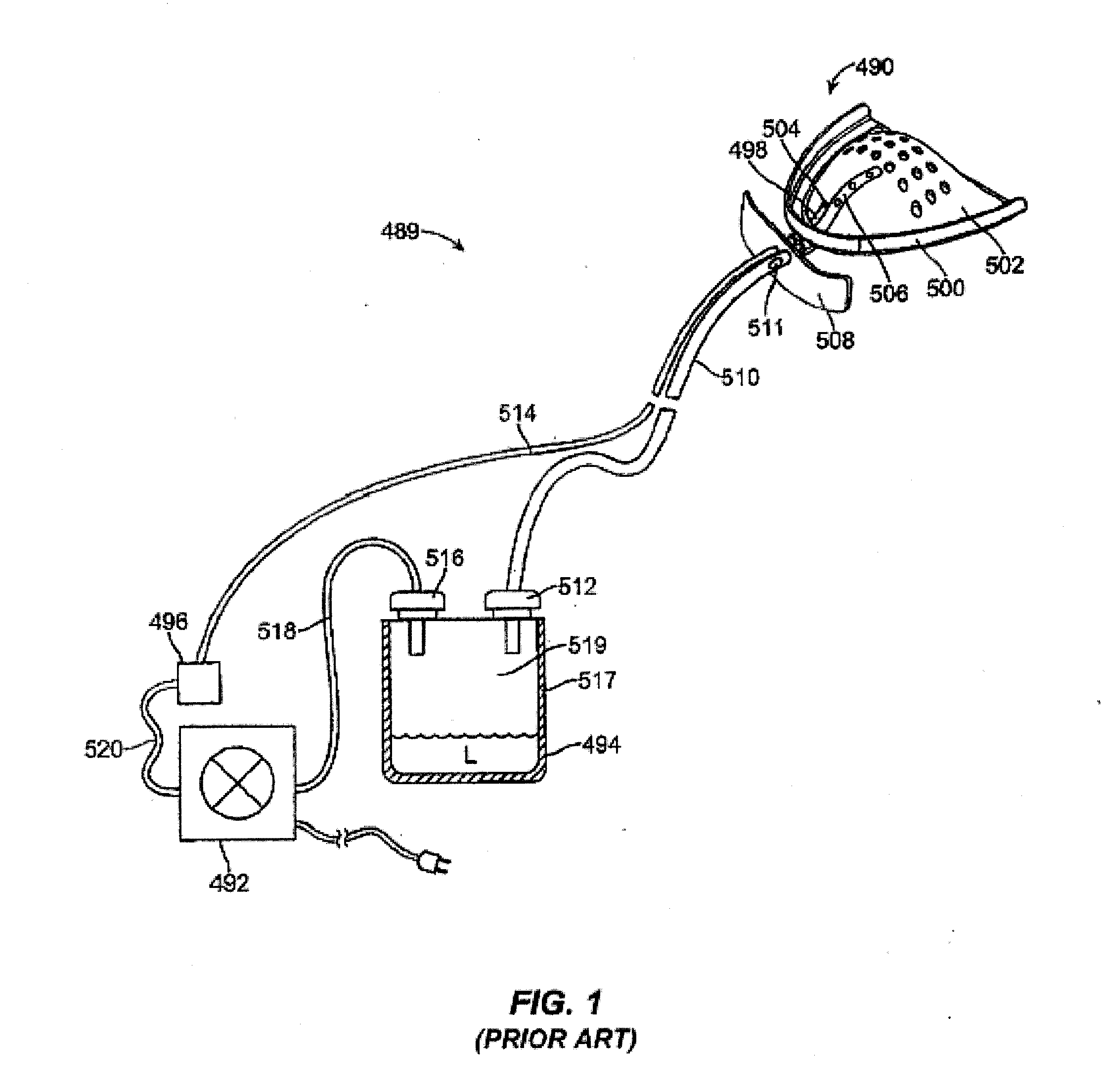
[0046]The saliva collectors and reservoirs of the present disclosure may be used in a variety of systems, typically systems where a vacuum line is being used to withdraw an air stream from a patient's oral cavity. Exemplary of such systems is system 489 illustrated in FIG. 1 where the reservoirs of the present invention might be used in place of conventional saliva reservoir 494.

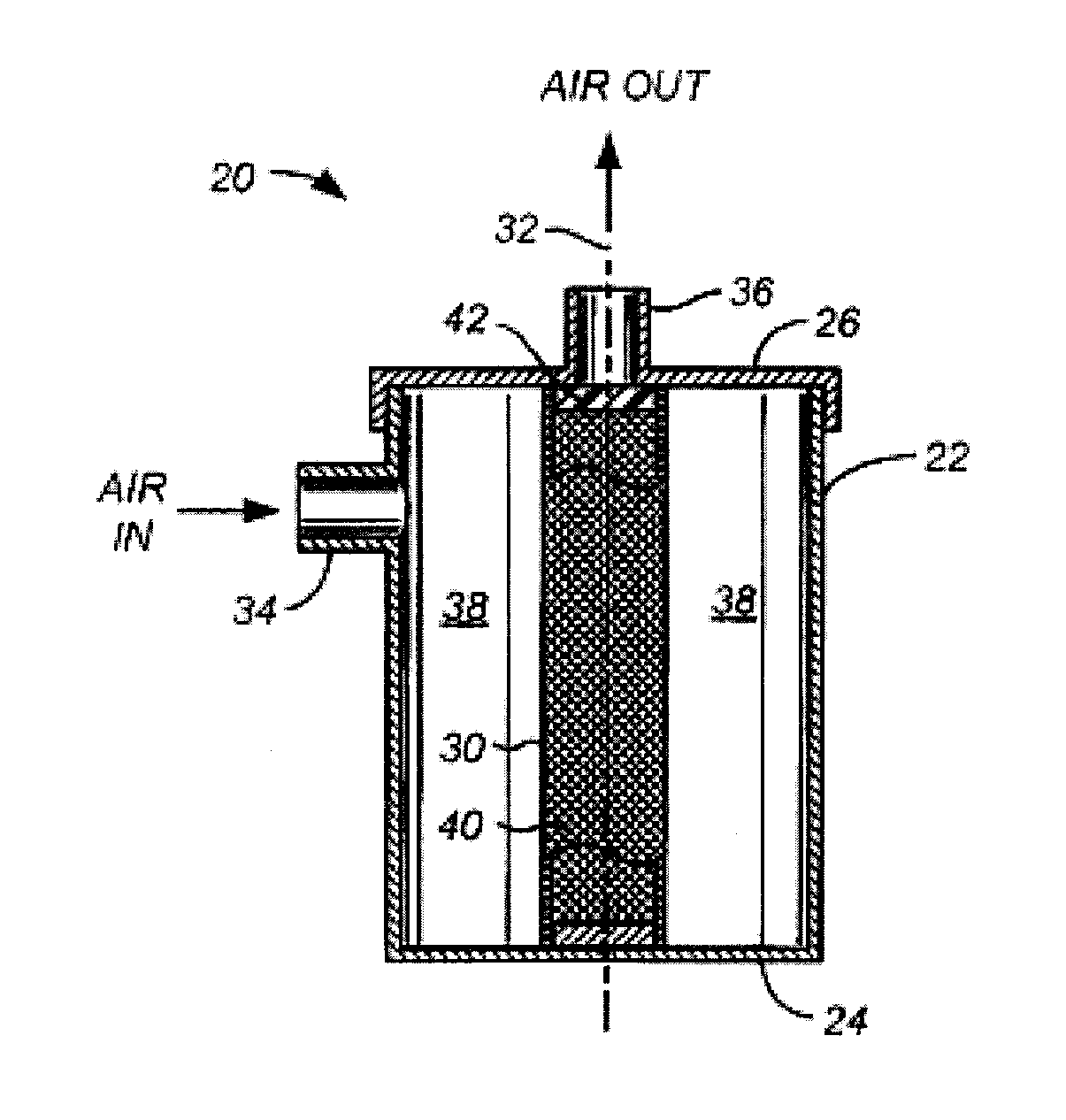
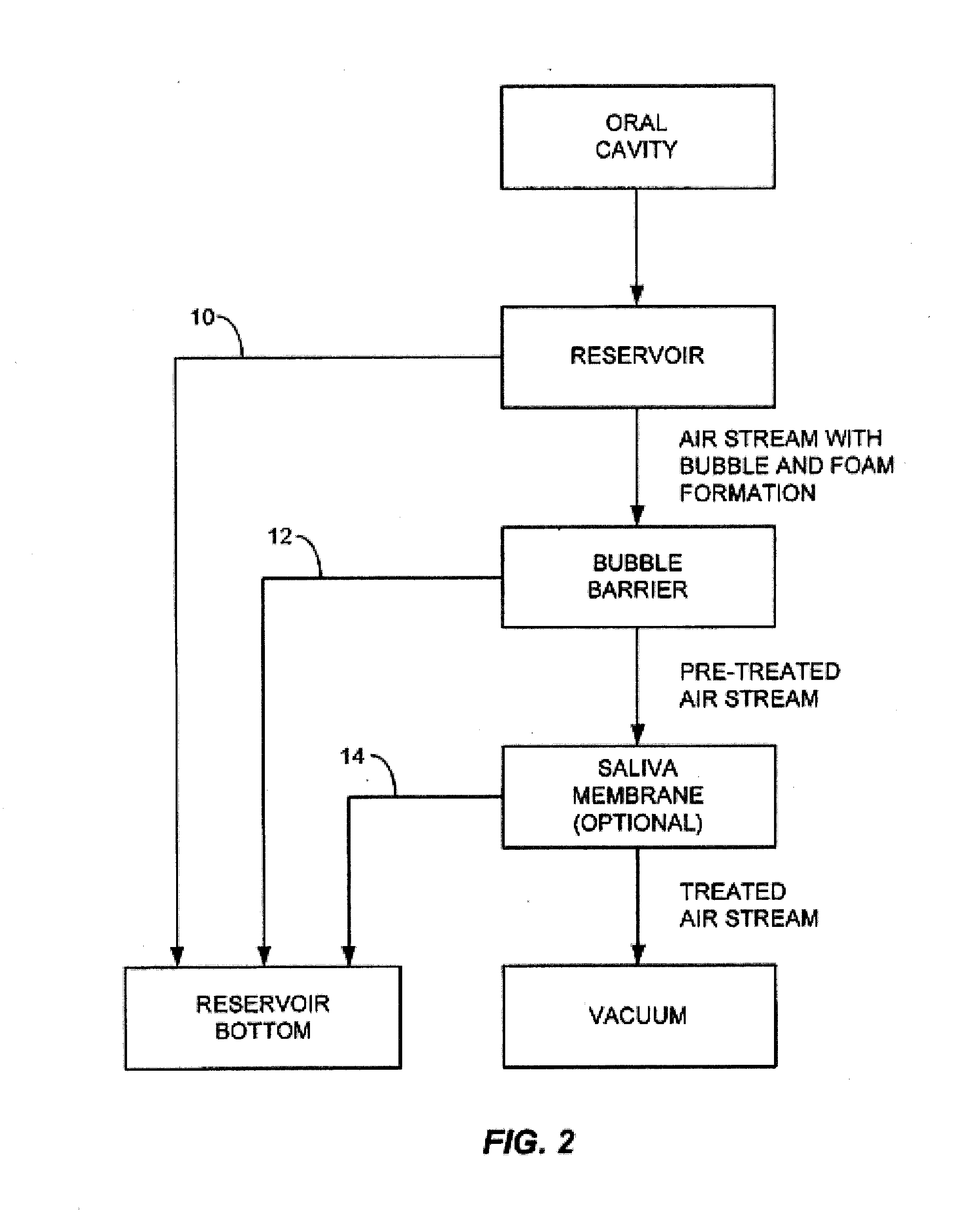
[0047]Referring to FIG. 2, the apparatus and methods of the present disclosure provide for drawing an air stream from an oral cavity using a vacuum source, such as a pump. The air stream first passes into a reservoir where a first volume 10 of saliva separates by gravity and falls to the reservoir bottom. The remaining air stream will typically have entrained bubbles and saliva foam which is to be removed before the air stream reaches a saliva membrane to remove entrained liquid saliva. The removal of the bubbles and foam is accomplished with a bubble barrier to produce a pre-treated air stream which is then...


PUM


Abstract

A saliva collector comprises a reservoir and a flow path from an inlet to an outlet on the reservoir. A heating element is disposed along the flow path. The heating element applies heat to force bubbles and foam present in the air aspirated from a patient's oral cavity to collapse. The collapsed bubbles and foam evaporate or drain into the reservoir bottom as liquid saliva.

Description

CROSS-REFERENCE[0001]This application claims the benefit of U.S. Provisional Application No. 61 / 831,833, filed Jun. 6, 2013 (Attorney Docket No. 41506-712.101), which application is incorporated herein by reference.BACKGROUND[0002]1. Field of the Invention[0003]The present invention relates generally to medical devices and methods. In particular, the present invention relates to a reservoir and methods for its use for the collection of saliva with a reduction in bubbling and foaming.[0004]A vacuum may be applied to an appliance or device held in a patient's oral cavity for a variety of purposes. For example, an appliance for treating obstructive sleep apnea (OSA) may utilize a device held in a patient's mouth where a vacuum is constantly drawn on the device in order to reposition portions of the patient's oral anatomy to reduce the likelihood of OSA. The device may be used for or in conjunction with drawing a patient's tongue and / or lower mandible forward in order to reduce OSA. Of ...

Claims


Application Information

Patent Timeline
Patent Type & Authority Applications(United States)
IPC IPC(8): A61M1/00A61C17/06A61F5/56
CPCA61C17/046A61M1/0001A61F5/566A61M1/0023A61M2205/3653A61M2202/0466A61M1/0049A61C17/065A61M1/784A61M1/60
Inventor PODMORE, JONATHAN L.CROWE, JOHN EDWARDSVITALE, NICHOLAS R.DE LA PAZ, JR., FRANCISCOLOVELACE, ROBERT CURTISMONTGOMERY, PAYNE MCQUEENKOZLOWSKI, THOMAS DUNCAN
Owner APNICURE
Why Eureka
Try Eureka