Bicycle transmission

a technology for bicycles and transmission mechanisms, applied in vehicle transmission, vehicle components, rider propulsion, etc., can solve the problems of affecting the steering of the bicycle, limiting the speed of a given wheel size, and the pedals can be operated efficiently by the rider's legs, so as to achieve the effect of preventing contamination, preventing slipping, and ensuring safety

Inactive Publication Date: 2014-12-11
THOMPSON ROBERT WILLIAM
View PDF2 Cites 17 Cited by
  • Summary
  • Abstract
  • Description
  • Claims
  • Application Information

AI Technical Summary

Benefits of technology

[0013]The bicycle transmission mechanism suitably uses only rotary joints which can readily be sealed to retain lubricant and keep out contamination, providing a high efficiency zero maintenance mechanism. The pedal arms require no external lubrication and only reciprocate adjacent to the rider's legs and therefore will not snag or soil the riders clothing. The absence of externally lubricated components is a particular advantage to a bicycle designed to be folded and carried.
[0014]The geometry of the pedal arms, cranks and links results in a forward pedaling bias providing a comfortable and efficient pedaling action which is practical to use with a free wheel mechanism. The pedal arm mechanisms, being mounted from the frame adjacent to the rear wheel, allow rear suspension to be readily incorporated, using a simple pivoting joint, forward of the rear wheel, on the frame of the bicycle.
[0015]Preferably the cranks are connected to the wheel of the bicycle by a multi ratio gear and free wheel mechanism allowing comfortable and efficient riding over a range of riding conditions.
[0016]Preferably the multi ratio gear mechanism is fitted within the wheel hub of the bicycle and is sealed to retain lubricant and keep out contamination, so minimizing wear and eliminating the need for maintenance.
[0017]Preferably the multi ratio gear mechanism uses a number of epicyclical gear stages connected in series, the input to each stage at the carrier and the output at the ring gear, providing high efficiency, the ratios of the stages configured to give consistent ratio changes on shifting, to provide a consistent feel to the rider, and to cover the required range of ratios with a minimum number of ratios while maintaining close ratio shifts.
[0018]Preferably the gear ratios are selected by controllable pawls acting on ratchet wheels to selectively lock the sun gears of the epicyclical gear stages allowing shifting when the bicycle is stationary as well as when moving.

Problems solved by technology

This bicycle has the disadvantage of having no gearing, with the driven wheel rotating at the same frequency as the pedals, so limiting speed for a given wheel size since the rate, often referred to as cadence, at which pedals can be operated efficiently by the rider's legs, is limited.
While pedaling, forces from the rider's legs would therefore interfere with the steering of the bicycle, since the rider is seated on the frame of the bicycle but the pedals and drive mechanism are mounted on the forks.
This interaction between pedaling and steering therefore reduces stability and increases the skill and effort required to ride the bicycle.
This bicycle also had the disadvantage of not having a free wheel mechanism to allow a rider to rest their legs stationary on the pedals while the bicycle continues moving, for example on a decent.
In the case of this prior art bicycle, setting of the pedal in a starting position without rolling the bicycle forwards or backwards, which could be dangerous or impractical, especially when at a road junction, is not possible, as no free wheel mechanism is employed.
However, simple reversal of the mechanism from the prior art using a long link reaching upward and forward to the frame of the bicycle from the rear of the lever does not result in a practical mechanism.
This makes pedaling forward impractical when a free wheel mechanism is used, especially when standing on the pedals, where the rider's weight on the lower pedal holds it at the lowest point and stops the higher pedal passing it's highest point.

Method used


Image

  • Bicycle transmission
  • Bicycle transmission
  • Bicycle transmission

Examples


Embodiment Construction

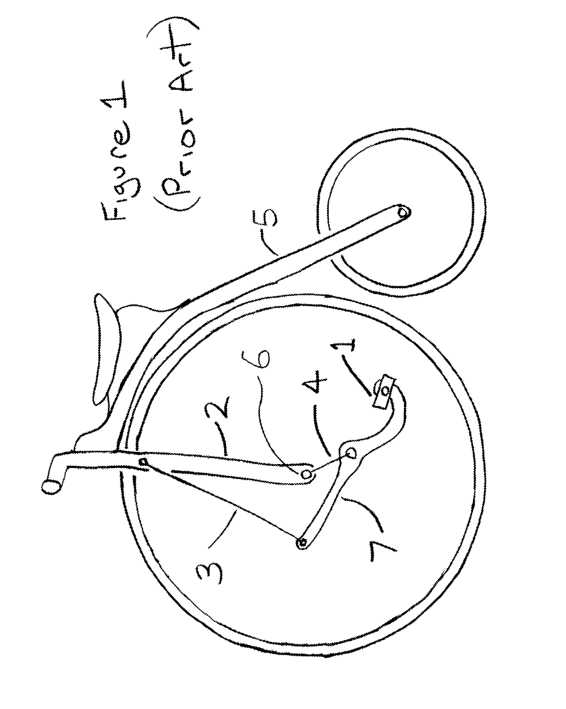
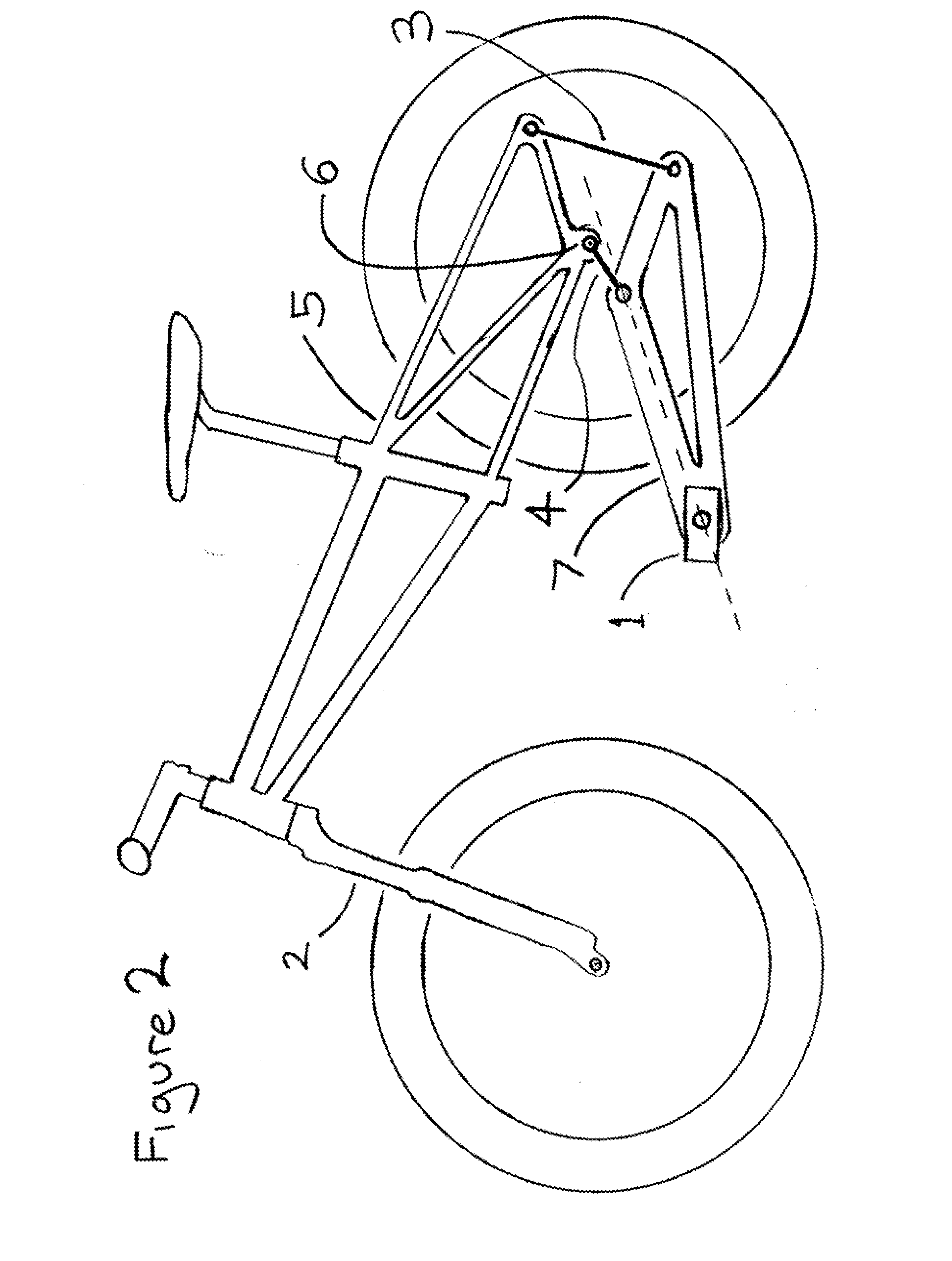
[0038]FIG. 2 shows a preferred embodiment of bicycle with the pedal arm and link geometry of the present invention. For clarity the mechanism from one side only of the bicycle is shown. A pedal 1 is mounted by a rotating joint to the forward end of a rigid pedal arm 7. The pedal arm is mounted by a rotating joint to a crank 4. The crank rotates around a crankshaft 6 which is mounted by a rotating joint to the frame 5. The pedal arm 7 is further connected to the frame by a link 3, the link having rotating joints at each end. It should be noted that the geometry of the pedal arm 7, has the connection to the link behind the connection to the crank and below a straight line, indicated by a dashed line in FIG. 2, through the pedal mounting position and the crank mounting position. This geometry requires the link to be substantially vertical to maintain reasonable angles between the link, to minimize forces in the link and the arm and to avoid the link crossing the center of the crank, an...


PUM


Abstract

A chainless drive mechanism for a bicycle using pedal arms, one on each side of the bicycle, each pedal arm carrying a pedal engageable with a rider's foot. Each pedal arm is mounted to a crank by a rotating joint and connected to the frame of the bicycle by a link, each link having rotating joints at each end. The cranks are connected by a shaft passing through the hub of to the driven wheel of the bicycle. The cranks may be connected to the driven wheel by a multi ratio free wheeling gear mechanism.

Description

CROSS REFERENCE TO RELATED APPLICATIONS[0001]This application claims the benefit of patent application GB1310092.0 entitled Bicycle Transmission and filed on Jun. 6, 2013; of which the entirety is incorporated herein by reference.BACKGROUND OF THE INVENTION[0002]1. Field of the Invention[0003]This invention relates to a drive mechanism / transmission mechanism for a bicycle.[0004]2. Background[0005]Bicycles commonly use roller chain transmissions, with multiple chain wheels and sprockets together with derailleur shifting mechanisms, to connect the pedals to a wheel. Roller chains wear and stretch in use and the sprockets, with which they engage, wear until they break, slip or otherwise fail, requiring expensive replacement. To minimize wear the mechanism needs regular cleaning and lubrication. This is especially the case for bicycles used off-road where contamination by abrasive matter is unavoidable. Roller chain mechanisms also suffer from a number of other problems, for example, th...

Claims


Application Information

Patent Timeline
Patent Type & Authority Applications(United States)
IPC IPC(8): B62M1/36
CPCB62M1/36B62M1/30B62M11/18B62M1/26B62M1/38B62M3/083
Inventor THOMPSON, ROBERT WILLIAM
Owner THOMPSON ROBERT WILLIAM
Why Eureka
Try Eureka