
Air quality controlled air filtering system

a filter system and air quality control technology, applied in the direction of filtration separation, auxillary pretreatment, separation processes, etc., can solve the problems of reducing affecting the overall filter life, and increasing downtown

Inactive Publication Date: 2014-12-18
ROBOVENT PROD GRP
View PDF2 Cites 4 Cited by
  • Summary
  • Abstract
  • Description
  • Claims
  • Application Information

AI Technical Summary

Benefits of technology

This patent is for an air filtering system that continuously measures the amount of suspended particulate matter in an area and adjusts the amount of air filtering needed in real-time to match the fluctuating levels of air contamination. The system is dynamic and efficient, only operating at the necessary capacity to filter the air. Overall, this patent provides a solution for improving air quality in workplaces, buildings, and other spaces.

Problems solved by technology

This is very inefficient, using energy needlessly, placing needless wear on the equipment, reducing overall filter life and increasing downtown due to the need for additional filter maintenance.
One type of unit equipped with speed adjustment control for the motors through the use of a variable frequency drive can vary the capacity and speed of the filtration unit, however, it is not based on a measure of particulates in the air.

Method used


Image

  • Air quality controlled air filtering system
  • Air quality controlled air filtering system
  • Air quality controlled air filtering system

Examples


Embodiment Construction

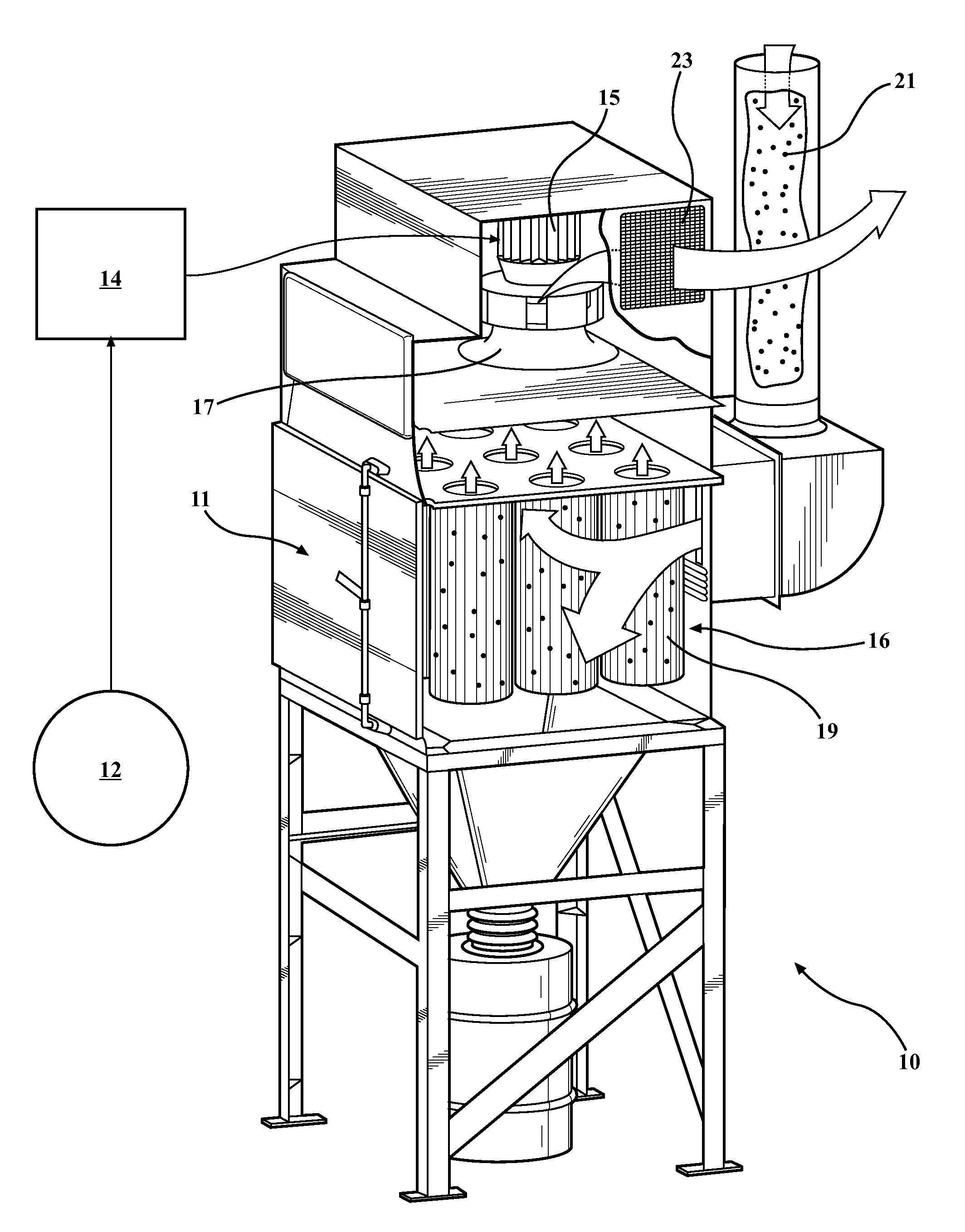
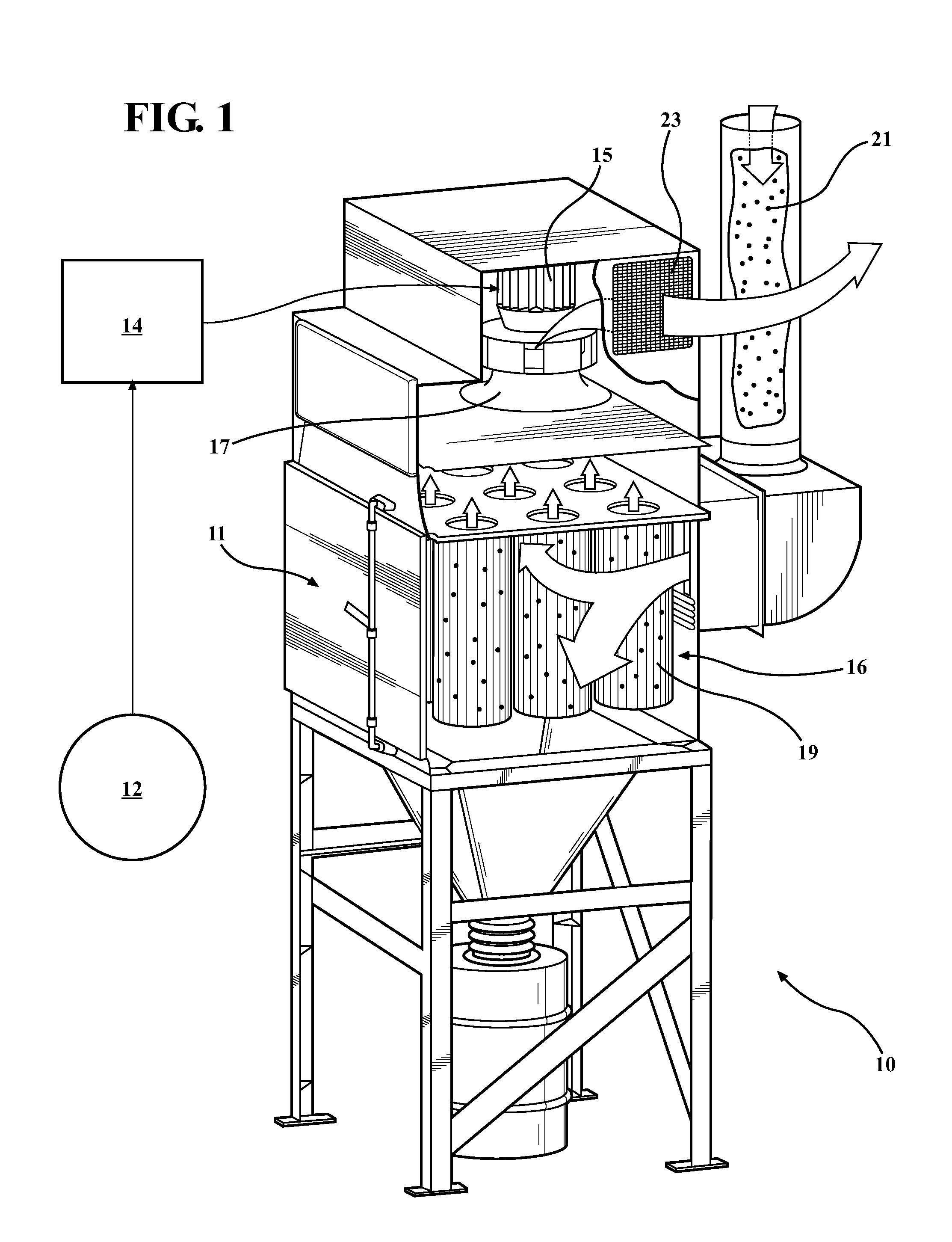
[0014]The present invention is shown generally at 10 in FIG. 1. FIG. 1 is a schematic representation of the air filtering system of the present invention.

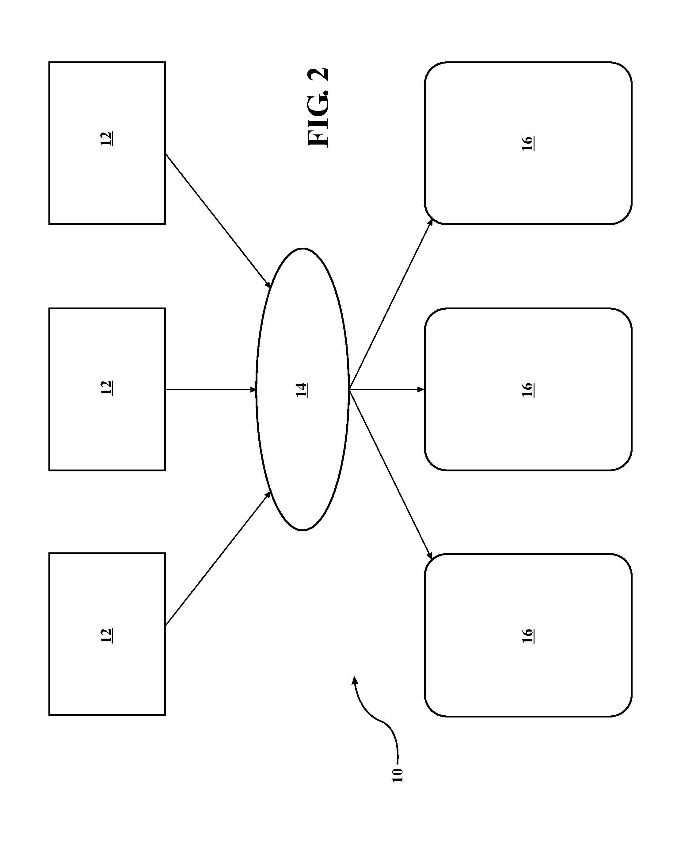
[0015]In the disclosed embodiment at least one air quality sensor 12 is positioned in a work area, such as a welding station, a workroom, an entire building etc. An example of an air quality sensor is a Remote 5014P airborne particulate counter, sold by Lighthouse Worldwide Solutions. It should be appreciated that depending upon the type and size of the work area, more than one air quality sensor may be desired.

[0016]The air quality sensor 12 may be of several types for example a particle counter, a dust, particulate or aerosol monitor or impactor probe, etc. There are a number of air quality sensors available on the market and one of ordinary skill in the art would know which would be most effective in a given work area.

[0017]The sensor 12 is operatively connected to a master control 14. An example of a master controller is a 6181...


PUM

PropertyMeasurementUnit
Speedaaaaaaaaaa

Abstract

The present invention provides an air filtering system and method that continuously monitors and samples the air to measure the amount or concentration of suspended particulate matter in an area. Based on the information collected the air filtering system determines the need for and the amount and volume of air filtering that is required. In this way, the air filtering system only operates at the needed capacity to filter the air, and dynamically responds in real time to the fluctuating air contamination levels that occur during various work processes within the space, room or building.

Description

RELATED APPLICATIONS[0001]This application claims benefit to provisional application No. 61 / 834,980, filed on Jun. 14, 2013, and titled Air Quality Controlled Air Filtering System.STATEMENT REGARDING FEDERALLY SPONSORED RESEARCH[0002]NONETECHNICAL FIELD[0003]This invention generally relates to an air filtering system and, more particularly, to an air filtering system that measures air quality in an enclosed space, such as an industrial or manufacturing facility, building, work area, workroom etc. and controls the activity and speed of the filtering unit / s for maximum efficiency.BACKGROUND OF THE INVENTION[0004]Air filtering systems are well known throughout several industries where maintaining a clean environment is important. For example, in vehicle manufacturing, welding processes are necessary for welding steel frames for vehicles. Typically, such welding processes are carried out in a work area wherein particulates are generated and infiltrate the air. The air filtering ventilat...

Claims


Application Information

Patent Timeline
IPC IPC(8): B01D46/44
CPCB01D46/442B01D46/2407B01D46/58
Inventor REID, JOHN
Owner ROBOVENT PROD GRP
Learn More