Image display apparatus and method of controlling same

a technology of image display and display screen, which is applied in the direction of instruments, computing, electric digital data processing, etc., can solve the problems of disturbance to the user, achieve accurate reproduction of input images, reproduce brightness of cursors, and reproduce input images accurately

Inactive Publication Date: 2014-12-18
CANON KK
View PDF25 Cites 11 Cited by
  • Summary
  • Abstract
  • Description
  • Claims
  • Application Information

AI Technical Summary

Benefits of technology

[0005]However, in an image editing display or a color management display used for checking posters, web designs, and the like, it is necessary to reproduce input images accurately. In an image output from a personal computer, an image of an object for assisting a user's operation such as a mouse cursor (hereinafter referred to as a cursor) is often superimposed on the original image that is to be reproduced accurately. When the control of changing the brightness of the backlight and the transmittance of the liquid crystal is applied to such an image based on the image signals of the respective image regions, the brightness of the cursor is also reproduced accurately. As a result, when the cursor is placed on a dark region of the original image, a light source corresponding to the region where the cursor is present is lit bright in order to reproduce the brightness of the cursor accurately. Moreover, when the light source corresponding to the region where the cursor is present is lit bright, light may leak into the surrounding regions (this leakage is referred to as “halo effect” in the present specification), which may cause a sense of disturbance to the user.

Problems solved by technology

Moreover, when the light source corresponding to the region where the cursor is present is lit bright, light may leak into the surrounding regions (this leakage is referred to as “halo effect” in the present specification), which may cause a sense of disturbance to the user.

Method used


Image

  • Image display apparatus and method of controlling same
  • Image display apparatus and method of controlling same
  • Image display apparatus and method of controlling same

Examples


first embodiment

[0024]Embodiments of the present invention will be described with reference to the drawings.

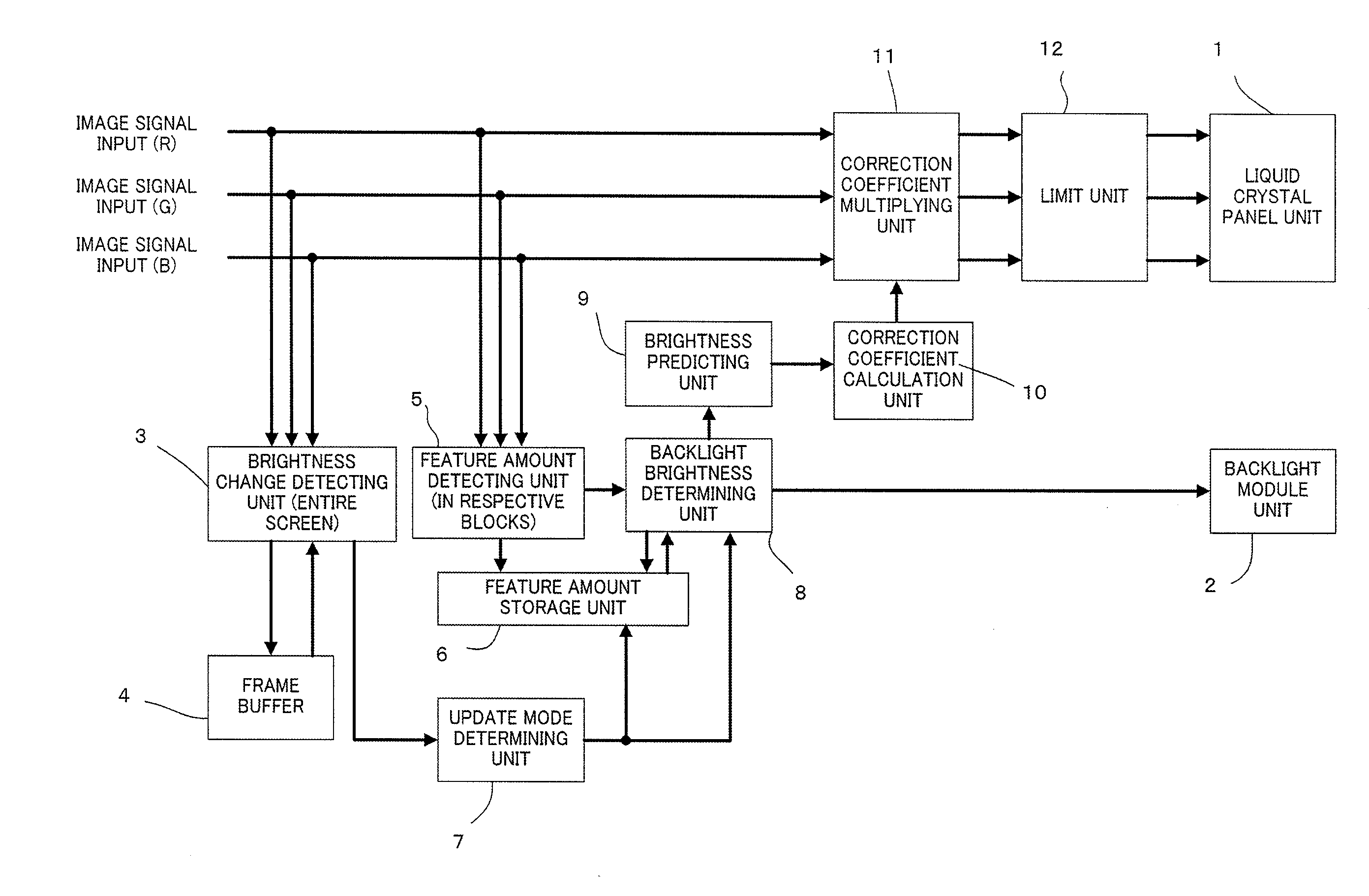
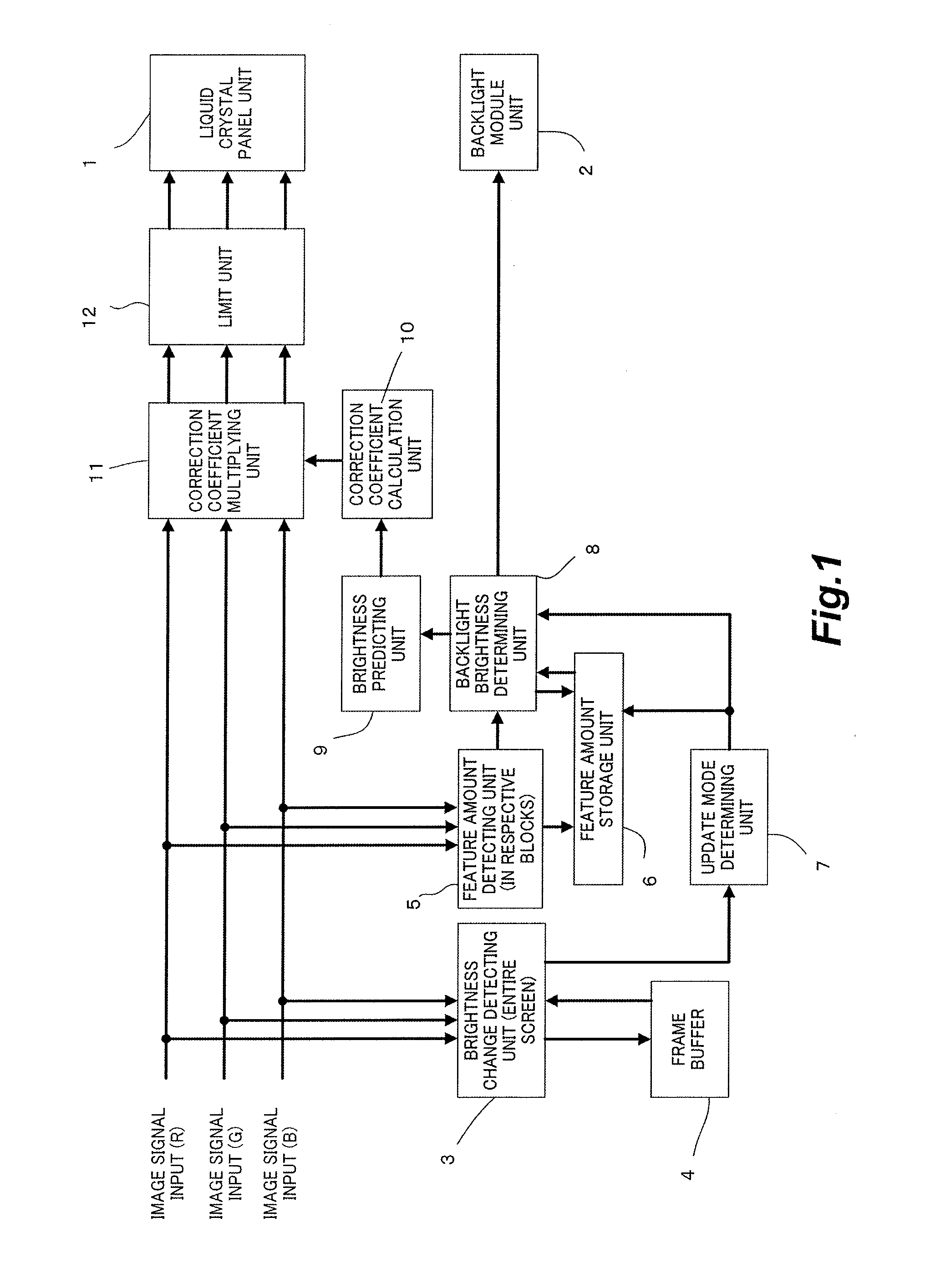
[0025]An image display apparatus according to a first embodiment calculates the number of pixels (hereinafter referred to a motion amount) of which the brightness has changed among the pixels of the entire screen. The image display apparatus detects a cursor movement by determining whether the motion amount results from a cursor movement based on whether the motion amount is equal to or smaller than a largest number of pixels of which the brightness can change when an object (auxiliary object) for assisting a user's operation, such as a cursor (for example, a mouse cursor) moves. The image display apparatus generates a feature amount if no cursor were present in a current frame from a feature amount of the current frame and a stored feature amount of a past frame when the cursor movement is detected. The image display apparatus determines a brightness of a backlight from the generated feature...

second embodiment

[0058]In the first embodiment, the feature amount when no cursor was present in the current frame is calculated from the feature amount of the current frame and the stored feature amount of the past frame, and the backlight brightness to be applied to displaying of the current frame is determined based on the feature amount. In the second embodiment, the backlight brightness when no cursor was present in the current frame is calculated from the backlight brightness determined from the feature amount of the current frame and a past backlight brightness. By doing so, similarly to the first embodiment, an image display apparatus that performs local dimming control according to an input image to improve the contrast can suppress both the halo effect and the flicker effect when a high brightness cursor moves in a dark region of the image.

[0059]FIG. 7 illustrates a functional block diagram of an image display apparatus according to the second embodiment. The image display apparatus illust...

third embodiment

[0073]In the first and second embodiments, the number of pixels of which the brightness has changed between adjacent frames is counted, and the counted value is compared with a threshold to detect a scene in which a cursor has moved. In a third embodiment, the cursor itself is detected as an object to detect a scene in which the cursor has moved. Moreover, a feature amount when no cursor was present in the current frame is calculated from a feature amount of the current frame and a stored feature amount of a past frame, and a backlight brightness to be applied to displaying of the current frame is determined based on the feature amount. By doing so, similarly to the first and second embodiments, an image display apparatus that performs local dimming control according to an input image to improve the contrast can suppress both the halo effect and the flicker effect when a high brightness cursor moves in a dark region of the image. Moreover, since the cursor itself is recognized, erro...


PUM


Abstract

An image display apparatus includes: a light-emitting unit having a plurality of light sources capable of controlling emission brightness individually; a display unit that displays an image on a screen; and a control unit that controls the respective emission brightnesses of the respective light sources according to images of regions on the screen corresponding to the respective light sources. When a difference between an image of a subject frame and an image of a past frame earlier than the subject frame is caused from movement of a predetermined object, the control unit suppresses the emission brightness of a light source corresponding to an image region of the subject frame brighter than that of the past frame from changing from the emission brightness of a light source corresponding to this image region of the past frame.

Description

BACKGROUND OF THE INVENTION[0001]1. Field of the Invention[0002]The present invention relates to an image display apparatus and a method of controlling the same.[0003]2. Description of the Related Art[0004]In a liquid crystal display apparatus, there is a technique of forming a backlight by a plurality of light sources of which emission brightness can be changed individually, and of controlling the emission brightness of the light sources and the transmittance of liquid crystal in respective regions on the screen corresponding to the respective light sources, on the basis of an image to be displayed in the regions (for example, see Japanese patent laid-open publication No. 2002-99250). According to this technique, it is possible to suppress a black spot from being noticed in a dark image portion and to improve the contrast.SUMMARY OF THE INVENTION[0005]However, in an image editing display or a color management display used for checking posters, web designs, and the like, it is neces...

Claims


Application Information

Patent Timeline
Patent Type & Authority Applications(United States)
IPC IPC(8): G09G3/36
CPCG09G3/3611G09G3/3426G09G2320/0247G09G2320/0285G09G2320/0646G09G2320/066G09G2320/103
Inventor IKEDA, TAKESHI
Owner CANON KK
Why Eureka
Try Eureka