Glass processing device and bottom machine therefor for manufacturing glass containers

a glass container and processing device technology, applied in glass tempering devices, manufacturing tools, instruments, etc., can solve the problems of not being able to feed air or other gas into glass tubes, the wall thickness of blowing methods is variable, and the delamination tendency in some regions is not reduced, and the delamination tendency is noticeably reduced

Active Publication Date: 2014-12-25
SCHOTT PHARMA AG & CO KGAA
View PDF5 Cites 22 Cited by
  • Summary
  • Abstract
  • Description
  • Claims
  • Application Information

AI Technical Summary

Benefits of technology

[0044]The method according to the invention is further developed by feeding the gas flow into the glass container such that the gas undergoes laminar flow in the glass container and again exits the glass container. As a result of this, the glass container is continuously flushed, so that gaseous substances, in particular alkali borates, which vaporize owing to heating of the bottom region, when the glass container is severed from the remaining glass tube, and can diffuse in the delamination zone into the glass of the glass container, are entrained by the gas flow immediately after the vaporization process and transported out of the glass container. As a result of this, the vaporized substances are prevented from diffusing back into the glass and thereby bringing about a delamination of the glass. The gas flow coats the delamination zone with a certain protective or boundary layer.
[0045]The method according to the invention is further developed by rotation of the glass tube or glass container by the holding unit relative to a free end of the duct system when a flow of gas is fed into the glass tube or glass container. Owing to fabrication inaccuracies or dirt or owing to wear when the device according to the invention is operated, it can happen that the lengthwise axis of the last section is not in ideal alignment with the axis of rotation of the glass tube or glass container at the free end of the duct system or a valve positioned there, and / or confines an angle with the axis of rotation. Consequently, the gas flow will not be fed ideally into the glass tube, resulting in the creation of a non-rotationally symmetric flow within the glass tube or glass container, which can lead, in an unfavorable case, to dead spaces or turbulence, so that the delamination tendency in some regions is not reduced or is reduced only to an inadequate extent. When the glass tube or glass container is rotated as the gas flow is fed in, the effect of not having the gas flow ideally fed in is uniformly distributed, so that, in turn, a rotationally symmetric flow is created in the glass tube or glass container. In this way, the delamination tendency is noticeably reduced even for a gas flow that is not fed in ideally.

Problems solved by technology

However, the glass containers resulting from the blowing method have a wall thickness that varies greatly.
On account of the optical distortions resulting from this, automated product inspection is possible to only a very limited extent.
DE 103 41 300 B3 shows a generic glass processing device for manufacturing glass containers from a glass tube; however, in this case, no air or other gas can be fed into the glass tube.
As already discussed, the free open end is already completely processed, but the bottom of the now resulting glass container is not yet in its desired form.
To this end, a gas flow is fed into the glass container, resulting in the creation of back pressure when it meets the bottom and pressing the bottom against the bottom template.
As a result of this, strong thermal stresses are created in the glass container, leading to potential cracking of the glass container after cooling.
This poses a problem in that Na ions can migrate into the substance stored in the glass containers.
Particularly in the case of pharmaceutical substances, this is undesirable.
Consequently, the flow conditions change in the region between the bottom tube and the inlet opening, so that it is nearly impossible to feed a reproducible gas flow from the pressure source into the glass container or glass tube.
Not only sodium borates, but alkali borates in general have yet another detrimental property.
However, the delamination tendency cannot be reliably lowered into uncritical ranges with known glass processing devices and, for a long time, was not the focus of manufacturers of glass containers for the above-mentioned purposes.
Furthermore, particles and other foreign matter can accumulate in the gap, something that is not unlikely owing to the extreme conditions that prevail in the surroundings of the bottom machine during glass manufacture.
Consequently, unpredictable vortexes, turbulence, and splitting of the gas flow arise in the gap, so that only a portion of the gas flow is indeed fed into the tube running perpendicular.
Therefore, it is not possible to make any reproducible statements about the volume flow that is actually fed into the glass container or into the glass tube.
This is made possible by the gap-free design of the duct system, which could not be achieved in conventional duct systems.
If the first angle of the extension of a rotor or stator section is chosen to be too large, the region toward the neighboring subduct in which the gap seal can produce its effect is too small, so that the sealing effect of the gap seal could be lost.
If the tube is not aligned with the axis of rotation of the glass tube or glass container or if the tube confines an angle with the axis of rotation, the gas flow will not be fed ideally into the glass tube or into the glass container and a non-rotationally symmetric flow is created within the glass tube or glass container, which, in an unfavorable case, can lead to dead spaces or turbulence.
In addition, known parent machines can be used, so that the added structural expense is limited to the bottom machine.
Consequently, the gas flow will not be fed ideally into the glass tube, resulting in the creation of a non-rotationally symmetric flow within the glass tube or glass container, which can lead, in an unfavorable case, to dead spaces or turbulence, so that the delamination tendency in some regions is not reduced or is reduced only to an inadequate extent.

Method used


Image

  • Glass processing device and bottom machine therefor for manufacturing glass containers
  • Glass processing device and bottom machine therefor for manufacturing glass containers
  • Glass processing device and bottom machine therefor for manufacturing glass containers

Examples


Embodiment Construction

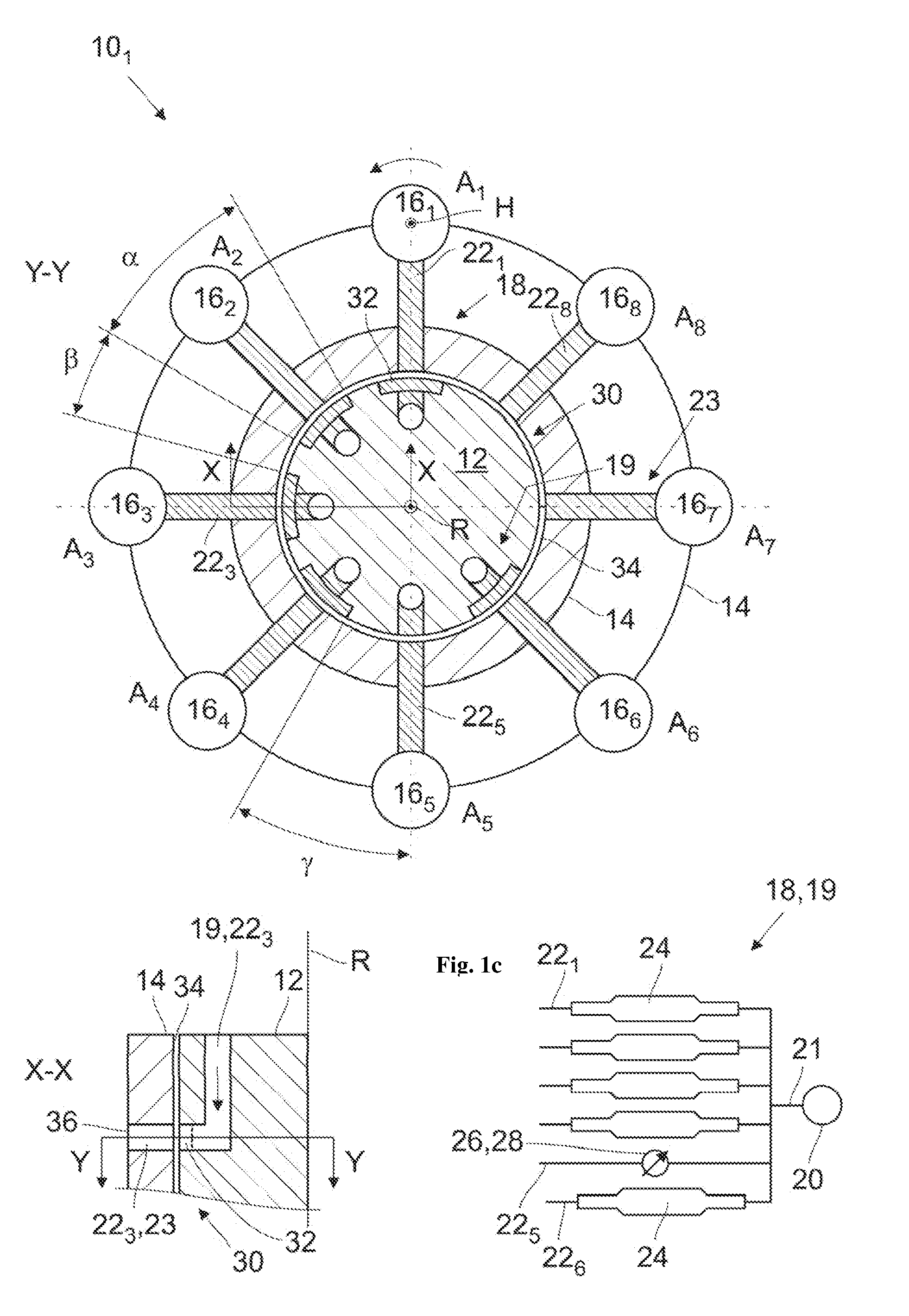
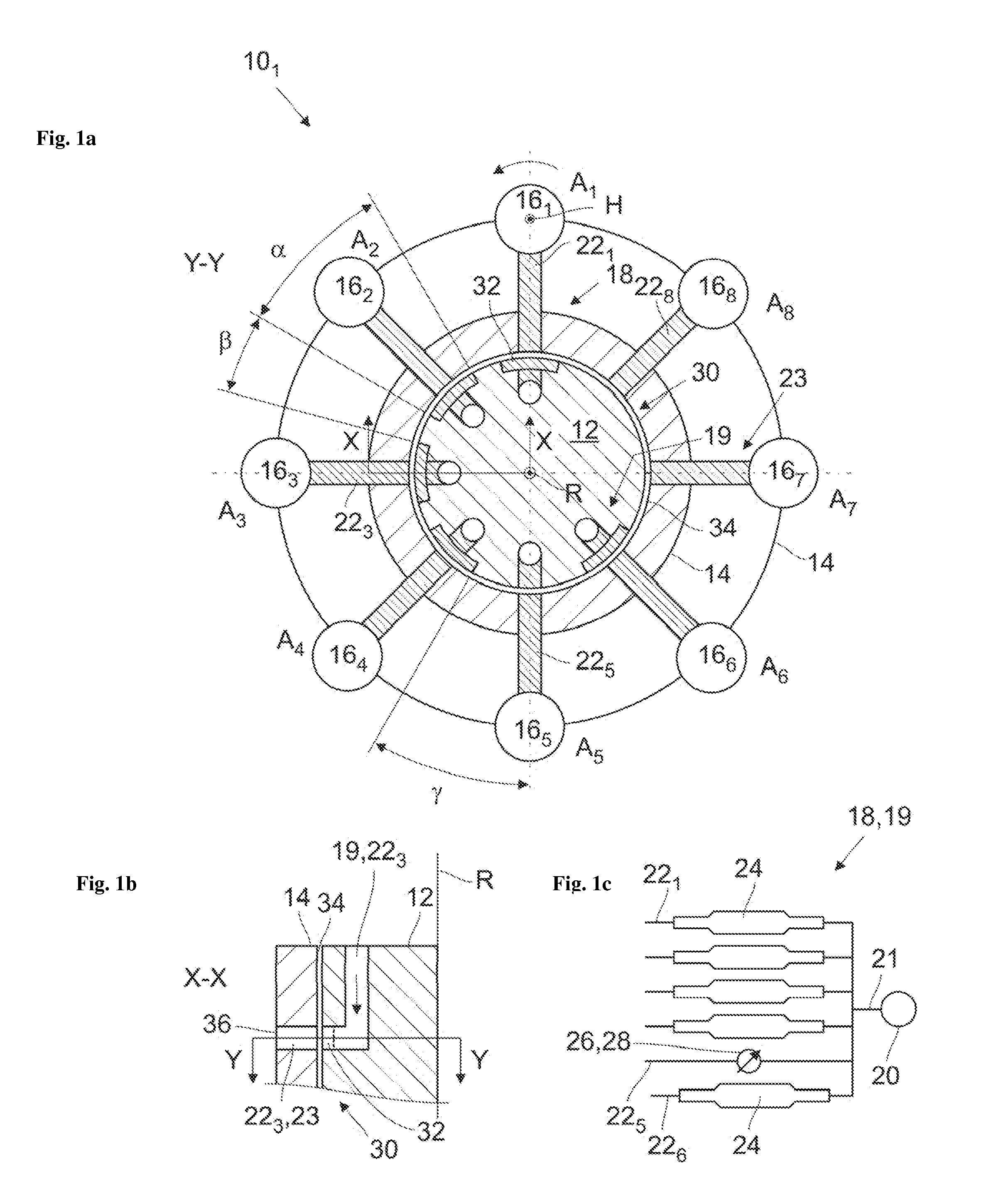
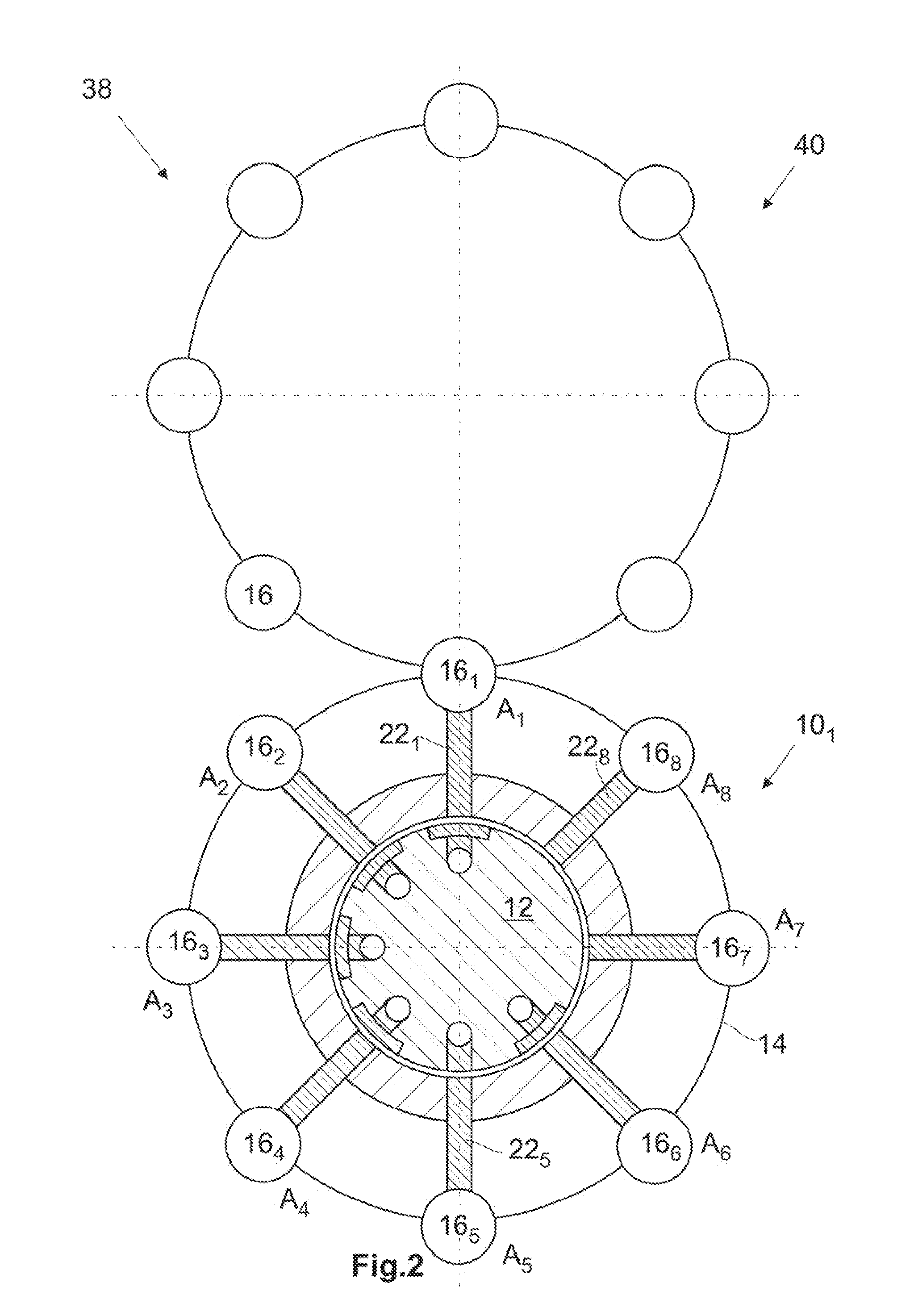
[0056]Illustrated in FIG. 1a is a bottom machine according to the invention, 101, in accordance with a first exemplary embodiment. The bottom machine 101 has a stator 12 and a rotor 14, which is arranged radially outside of the stator 12. The rotor 14 is arranged concentrically to the stator 12 and can rotate by means of a drive unit, which is not illustrated, around an axis of rotation R, which, during operation of the bottom machine 101, coincides essentially with the effective direction of the force of gravity. The rotor 14 comprises a number of holding units 16, each of which has a clamp chuck, which is not illustrated in greater detail, in which a glass tube, which is likewise not illustrated in greater detail, can be clamped. The holding unit or the clamp chuck can rotate around its own axis H. In the example illustrated, the rotor 14 has eight holding units 161 to 168. Furthermore, the bottom machine 101 has a duct system 18, with which a gas, such as, for example, air, can b...


PUM

PropertyMeasurementUnit
temperatureaaaaaaaaaa
lengthaaaaaaaaaa

Abstract

A bottom machine is provided for a glass processing device to manufacture glass containers from glass tubes. The bottom machine includes one or a plurality of holding units for holding the glass container or glass tube, with the holding units being mounted so as to rotate around an axis of rotation of the bottom machine in order to convey the glass container or glass tube to various processing positions, a pressure source for supplying a gas flow, a duct system communicating with the pressure source for directing the gas flow to the holding units and for feeding the gas flow into the glass tube or into the glass container, with the duct system being designed to be free of gaps.

Description

CROSS REFERENCE TO RELATED APPLICATIONS[0001]This application claims benefit under 35 U.S.C. §119(a) of German Patent Application No. 10 2013 212 150.4, filed Jun. 25, 2013, the entire contents of which are incorporated herein by reference.BACKGROUND OF THE INVENTION[0002]1. Field of the Invention[0003]The present invention relates to a bottom machine for a glass processing device for manufacturing glass containers made from a glass tube, comprising one or a plurality of holding units for holding the glass tube or glass container, with the holding units being mounted so as to rotate around their own axis and around an axis of rotation of the bottom machine in order to convey the glass tube to various processing positions, a pressure source for supplying a flow of gas, and a duct system that communicates with the pressure source for directing the gas flow to the holding units and for feeding the gas flow into the glass tube or glass container. The invention further relates to a glass...

Claims


Application Information

Patent Timeline
Patent Type & Authority Applications(United States)
IPC IPC(8): C03B9/38
CPCC03B9/3841C03B9/3866C03B9/3816C03B23/112
Inventor MOSELER, DORISFROST, ROBERTLANGE, ULRICHMARKOVIC, BOBANRUPERTUS, VOLKERHLADIK, BERNHARD
Owner SCHOTT PHARMA AG & CO KGAA
Why Eureka
Try Eureka