
Patch panel pivoting tray cable retention mechanisms

a technology of cable retention mechanism and patch panel, which is applied in the direction of fibre mechanical structure, instruments, optics, etc., can solve the problems of lc having a 1.25 mm diameter ferrule, affecting so as to facilitate the placement of multiples

Active Publication Date: 2014-12-25
GOFOTON HLDG
View PDF11 Cites 30 Cited by
  • Summary
  • Abstract
  • Description
  • Claims
  • Application Information

AI Technical Summary

Benefits of technology

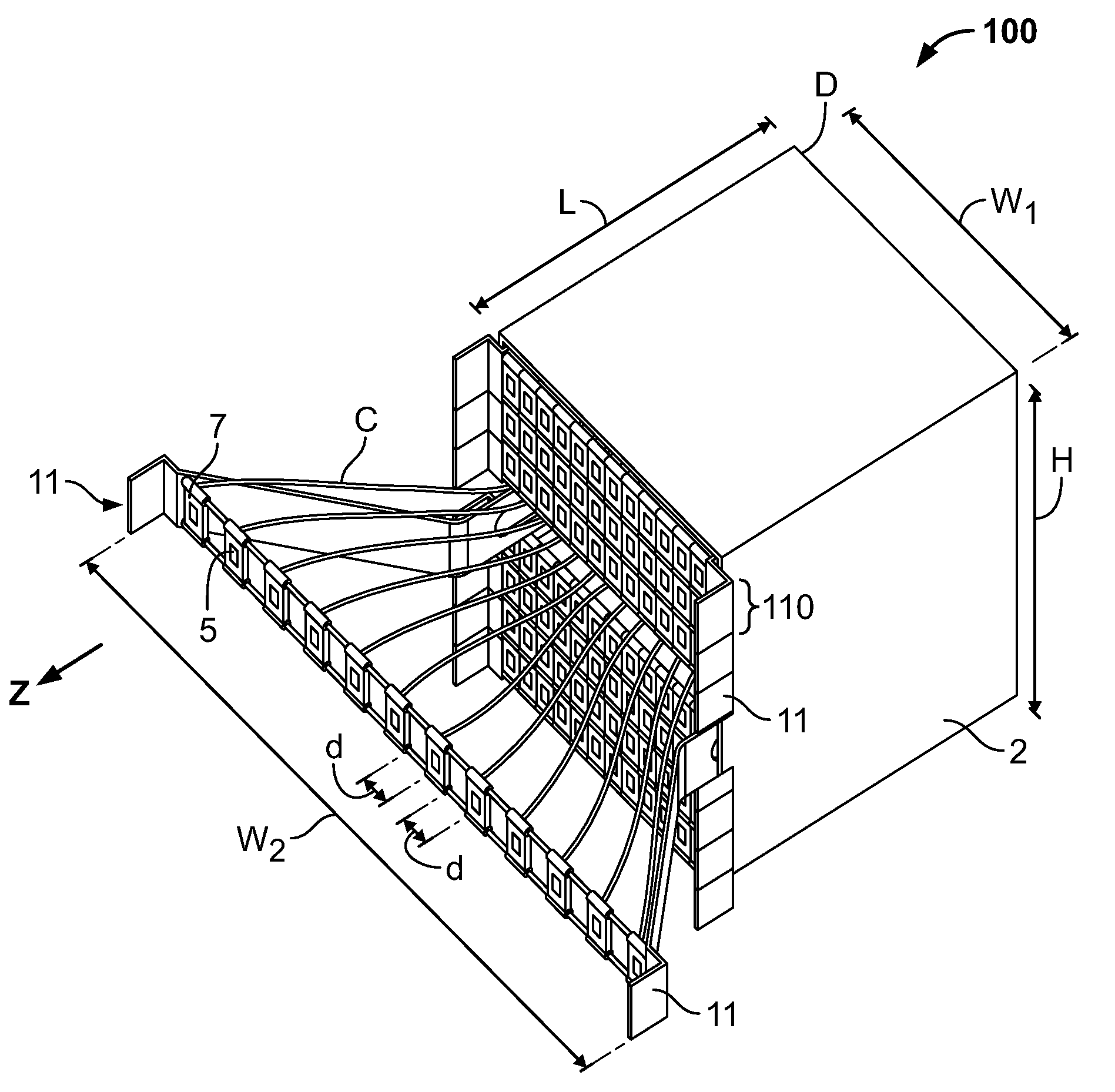
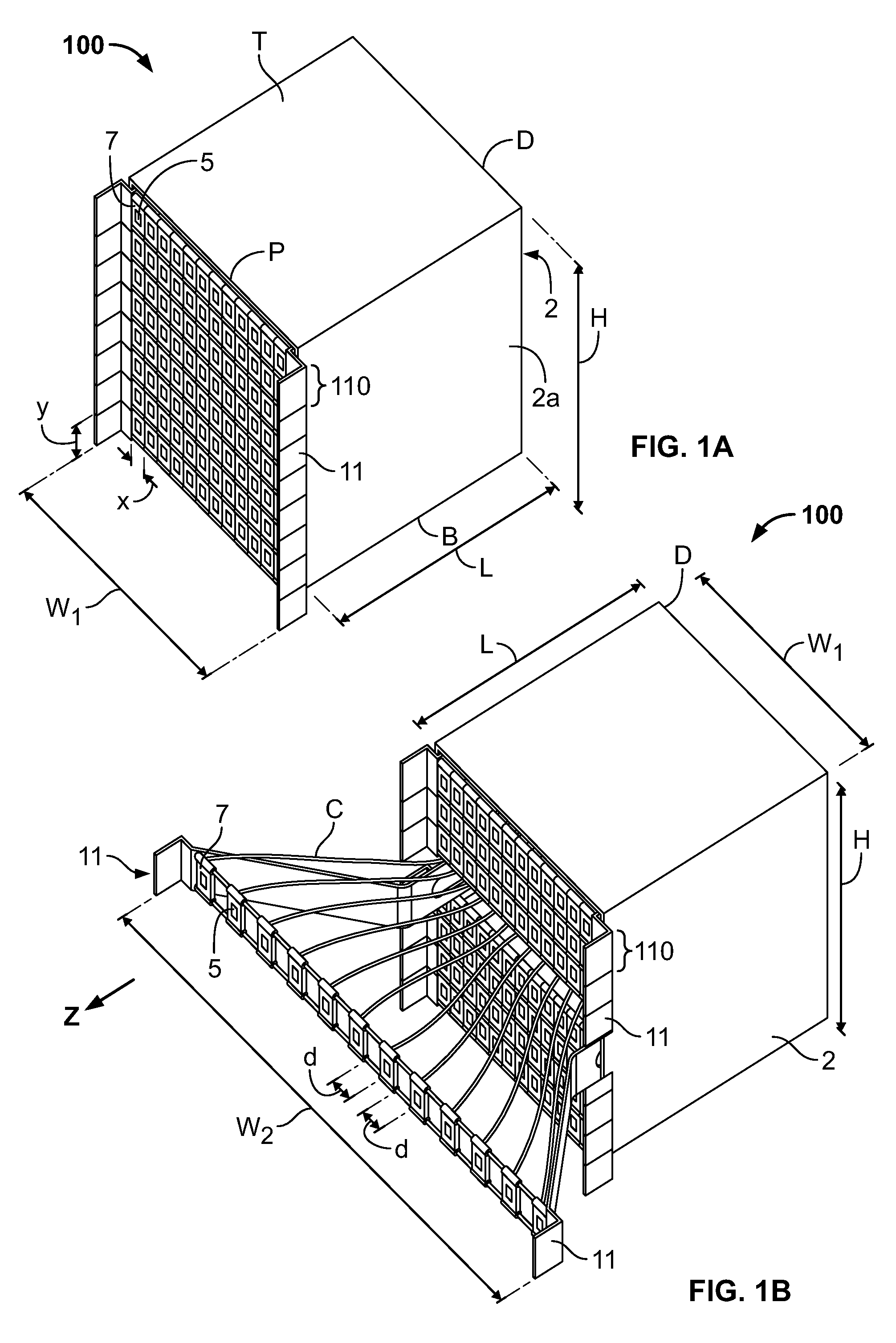
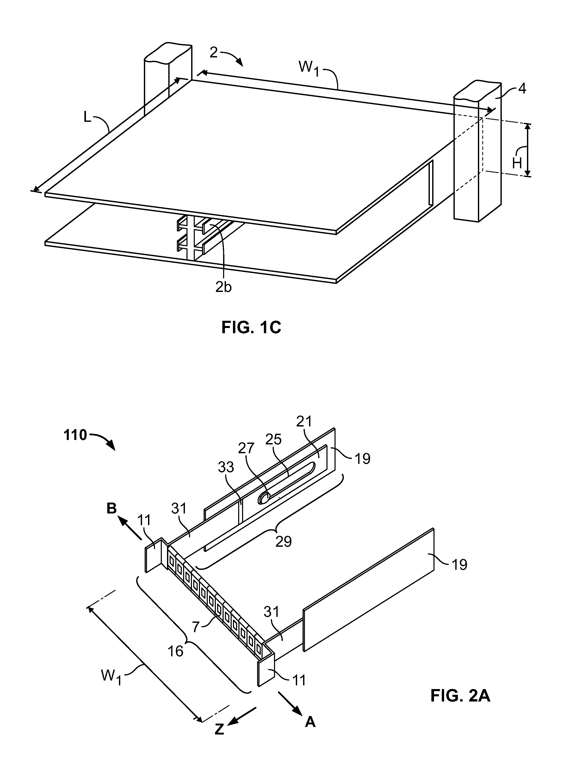
The present disclosure relates to communication patch panels and patching systems. Specifically, it describes apparatus for use with devices having a tray and multiple ports for connecting to cables. The apparatus includes a proximal arm and a distal segment that are pivotably attached to each other, allowing for easy placement and manipulation of the connectors. The apparatus also includes a cable retainer for guiding the cables. When in an installed state, the tray, cable retainer, and arm can rotate around the housing, providing flexibility in the installation and maintenance of the patch panel. The technical effects include improved ease of installation and maintenance of communication patch panels.

Problems solved by technology

However, there are disadvantages associated with using smaller connectors.
As more connectors are placed within the same amount of space, accessing the connectors which is often performed by hand may present a challenge.
Therefore, the use of small connectors, such as the LC having a 1.25 mm diameter ferrule, may be especially problematic for technicians having larger or less dexterous hands.

Method used


Image

  • Patch panel pivoting tray cable retention mechanisms
  • Patch panel pivoting tray cable retention mechanisms
  • Patch panel pivoting tray cable retention mechanisms

Examples


second embodiment

[0070]a communication patch panel system 400 incorporating a cable management system is shown in FIGS. 5A-D. Patch panel device 410 may be pivotally engaged with housing 402 (FIG. 5A) through a pair of proximal arms 405 and a pair of distal arms 415. Proximal arms 405 may be similar or identical in structure to arms 305, each proximal arm 405 having a proximal section, a distal section, three pivot points, and a rod 408 coupling the arms 405 to the housing 402. Proximal arms 405 may also be similar or identical in function to arms 305, providing support for, and guiding movement of, patch panel device 410 and tray 431.

[0071]Each distal arm 415 maybe similar or identical to the proximal arms 405, although sizes and shapes of the components of distal arms 415 may vary in relation to proximal arms 405 to support the function thereof. For example, each distal arm 415 may include a proximal segment 416 and a distal segment 417. The arms 415 each include first, second, and third pivot or ...

third embodiment

[0076]a communication patch panel system 500 incorporating a cable management system is illustrated in FIGS. 6A-C. Communication patch panel system 500 may include a housing 502 identical in most or all respects to housing 402. For example, housing 502 may include one or more proximal arms 505 and one or more distal arms 515 identical in structure and function to proximal arms 405 and distal arms 415.

[0077]Proximal arms 505 operate substantially similar to arms 305; each proximal arm 505 may include a proximal segment 506 and distal segment 507, with first, second, and third pivot points P1, P2, and P3. The proximal arm 505 is pivotally attached to a proximal portion of the housing 502 at the first pivot point P1 through a connection rod extending through the distal segment 507 at the point P1 and a hole of a flange extending from the proximal side of the housing 502. The proximal and distal segments 506, 507 are pivotally engaged with each other at the second pivot point P2. The pr...


PUM


Abstract

A system may facilitate access to communication connectors that are supported within a housing. The system may include one or more of the devices, which each include a connection means supporting the connectors. The system may also include a device that manages, e.g., guides and supports cables that are operatively coupled to the connectors. The patch panel device may have at least one tray engageable with the housing and having a first position within the housing and a second position pulled out of the housing. A proximal arm may have a proximal segment pivotably coupled to a distal segment. The proximal and distal segments may be pivotably coupled to the tray and the housing, respectively. The system may include a cable retainer configured to guide the cables. As the tray transitions from the first position to the second position, the tray is capable of rotating with respect to the housing.

Description

CROSS-REFERENCE TO RELATED APPLICATIONS[0001]The present application claims the benefit of the filing date of U.S. Provisional Patent Application No. 61 / 838,635 filed Jun. 24, 2013, the disclosure of which is hereby incorporated by reference herein.BACKGROUND OF THE DISCLOSURE[0002]The present disclosure generally relates to a device and a system for supporting and managing communication connectors, adapters, and / or ports. More particularly, the present disclosure relates to communication patch panel devices and systems, which facilitate access to communication connectors, adapters, and / or ports supported by the devices and systems.[0003]In communications cabinets and racks, a multitude of cables are interconnected to one another through connectors, e.g., adapters. A cable organization unit typically has a tray or a shelf or a similar platform, which supports the connectors, e.g., adapters. Examples of cable organization units include patch panels.[0004]A patch panel houses cable co...

Claims


Application Information

Patent Timeline
Patent Type & Authority Applications(United States)
IPC IPC(8): G02B6/44
CPCG02B6/4452G02B6/3825G02B6/44528G02B6/44526G02B6/4453G02B6/3897
Inventor TAKEUCHI, KENICHIROLU, HAIGUANG
Owner GOFOTON HLDG
Learn More