Building panel with a mechanical locking system

Active Publication Date: 2015-01-01
VÄLINGE INNOVATION AB
View PDF12 Cites 101 Cited by
  • Summary
  • Abstract
  • Description
  • Claims
  • Application Information

AI Technical Summary

Benefits of technology

[0009]It is an object of certain embodiments of the disclosure to provide an improvement over the above described techn

Problems solved by technology

A drawback with the known systems is that a locking system comprising a displaceable tongue r

Method used


Image

  • Building panel with a mechanical locking system
  • Building panel with a mechanical locking system
  • Building panel with a mechanical locking system

Examples


Embodiment Construction

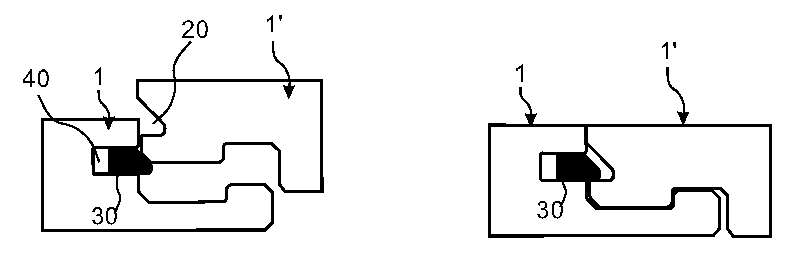
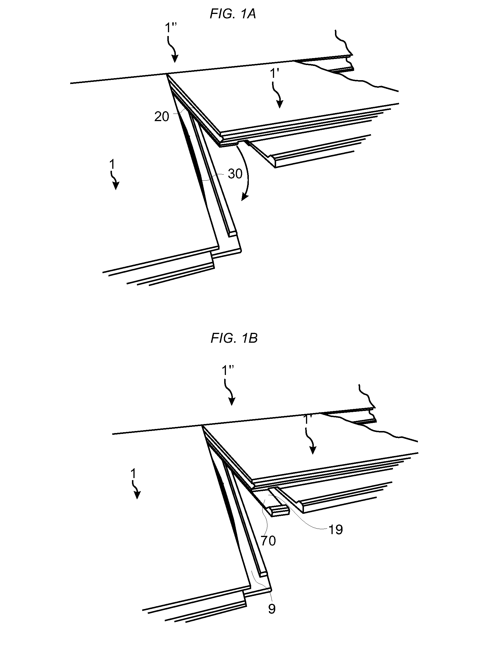
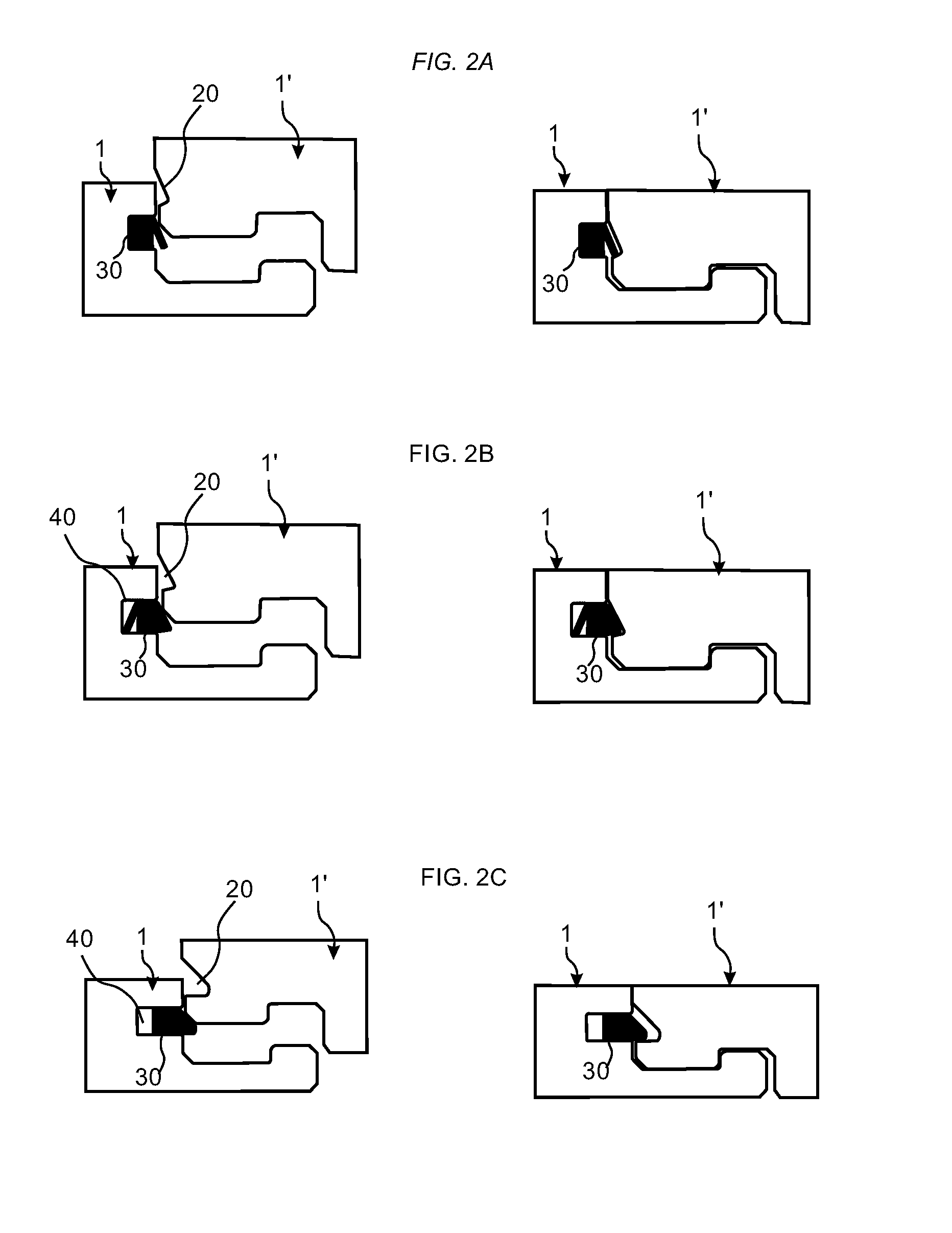
[0061]A known mechanical locking system for building panels, which comprises a displaceable tongue 30 at a first edge of a first panel 1 and a first tongue groove 20 at a second edge of a second panel 1′, is shown in FIGS. 1A-B. The displaceable tongue is configured to cooperate with the first tongue groove for locking in a vertical direction. The displaceable tongue 30 is a separate part and is made of, e.g., plastic, and inserted in a displacement groove at the first edge of the first panel 1. The tongue is pushed into a displacement groove during a vertical assembling of the first and the second edge of the first and the second panel. The displaceable tongue springs back and into a first tongue groove 20 at the second edge of the second panel 1′ when the panels have reached a locked position. A third and a fourth edge of the panels are provided with a locking system, which enables assembling to an adjacent panel 1″ by an angling movement, to obtain a simultaneous assembling of th...


PUM


Abstract

A set of essentially identical panels (1, 1′), such as building panels, provided with a mechanical locking system including a displaceable tongue (30), which is arranged in a displacement groove with a first opening at a first edge of a first panel (1). The displaceable tongue is configured to cooperate with a first tongue groove (20), with a second opening at a second edge of an adjacent second panel (1′), for vertical locking of the first and the second edge. The height of the first opening is greater than a second height of the second opening.

Description

CROSS REFERENCE TO RELATED APPLICATIONS[0001]The present application claims the benefit of Swedish Application No. 1350783-5, filed on Jun. 27, 2013, and of Swedish Application No. 1351323-9, filed on Nov. 8, 2013. The entire contents of each of Swedish Application No. 1350783-5 and Swedish Application No. 1351323-9 are hereby incorporated herein by reference in their entirety.TECHNICAL FIELD[0002]The disclosure relates to a panels, such as a building panels, floorboard, wall panels, ceiling panels, furniture components or the like, which are provided with a mechanical locking system.TECHNICAL BACKGROUND[0003]Building panels provided with a mechanical locking system comprising a displaceable and resilient tongue cooperating with a tongue groove for vertical locking is known and disclosed in, e.g., WO2006 / 043893 and WO2007 / 015669. The tongue is a separate part and is made of, e.g., plastic and inserted in a displacement groove at an edge of a panel. The tongue is pushed into the disp...

Claims


Application Information

Patent Timeline
IPC IPC(8): E04C2/40
CPCE04C2/40E04F15/02038E04F15/102E04F2201/0146E04F2201/0547E04F2201/0552E04F2201/0535E04F2201/023E04F2201/044
Inventor BOO, CHRISTIAN
Owner VÄLINGE INNOVATION AB
Why Eureka
Try Eureka