Propulsion bay

a technology for propellers and bays, applied in the field of propeller bays, can solve the problems of disadvantages of preceding known techniques,

Active Publication Date: 2015-01-01
CENT NAT DETUD SPATIALES C N E S
View PDF9 Cites 4 Cited by
  • Summary
  • Abstract
  • Description
  • Claims
  • Application Information

AI Technical Summary

Problems solved by technology

The preceding known techn...

Method used


Image

  • Propulsion bay
  • Propulsion bay
  • Propulsion bay

Examples


Embodiment Construction

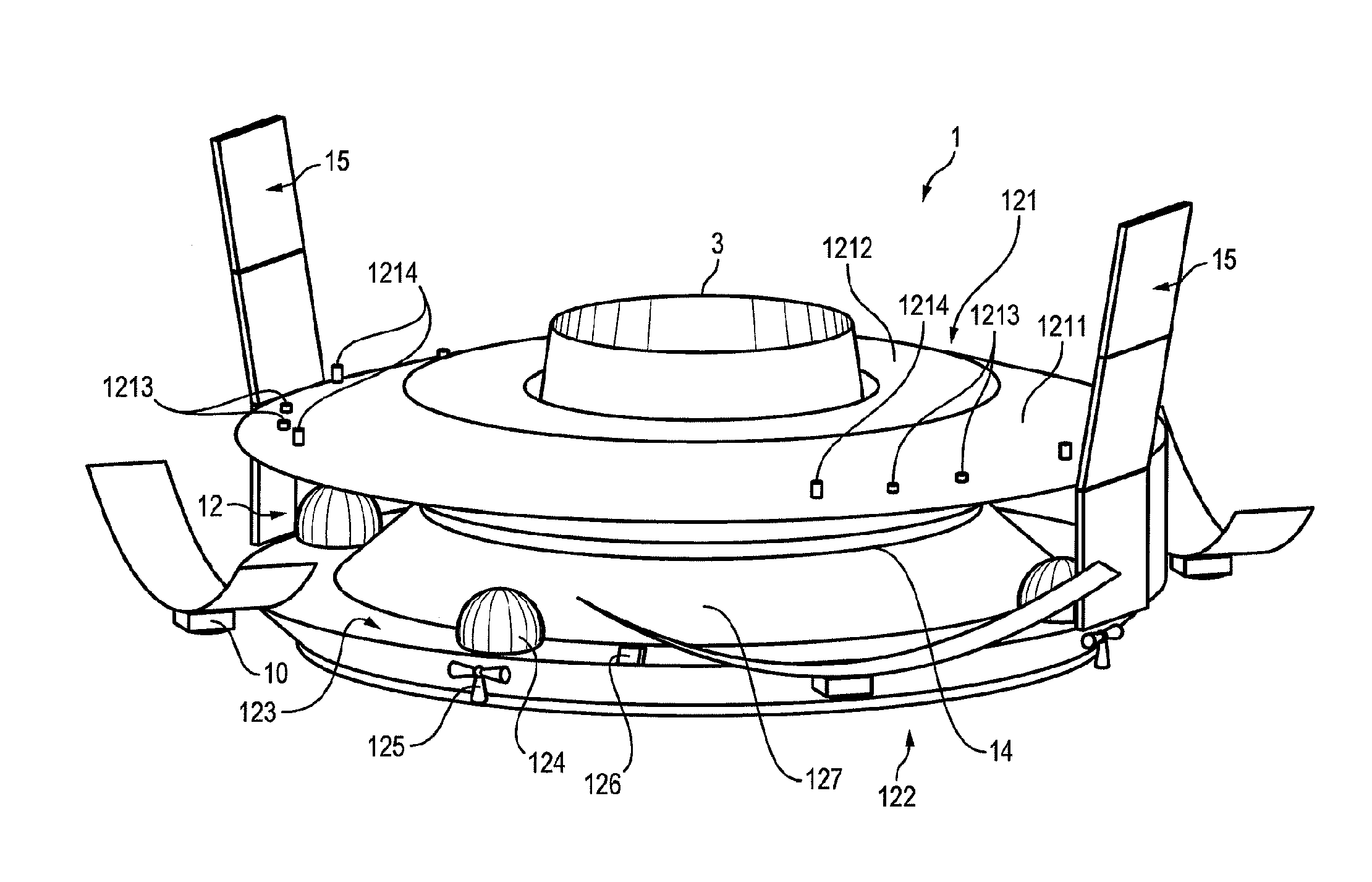
[0044]FIGS. 3 to 14 schematically illustrate one possible embodiment of a propulsion bay 1 according to the invention.

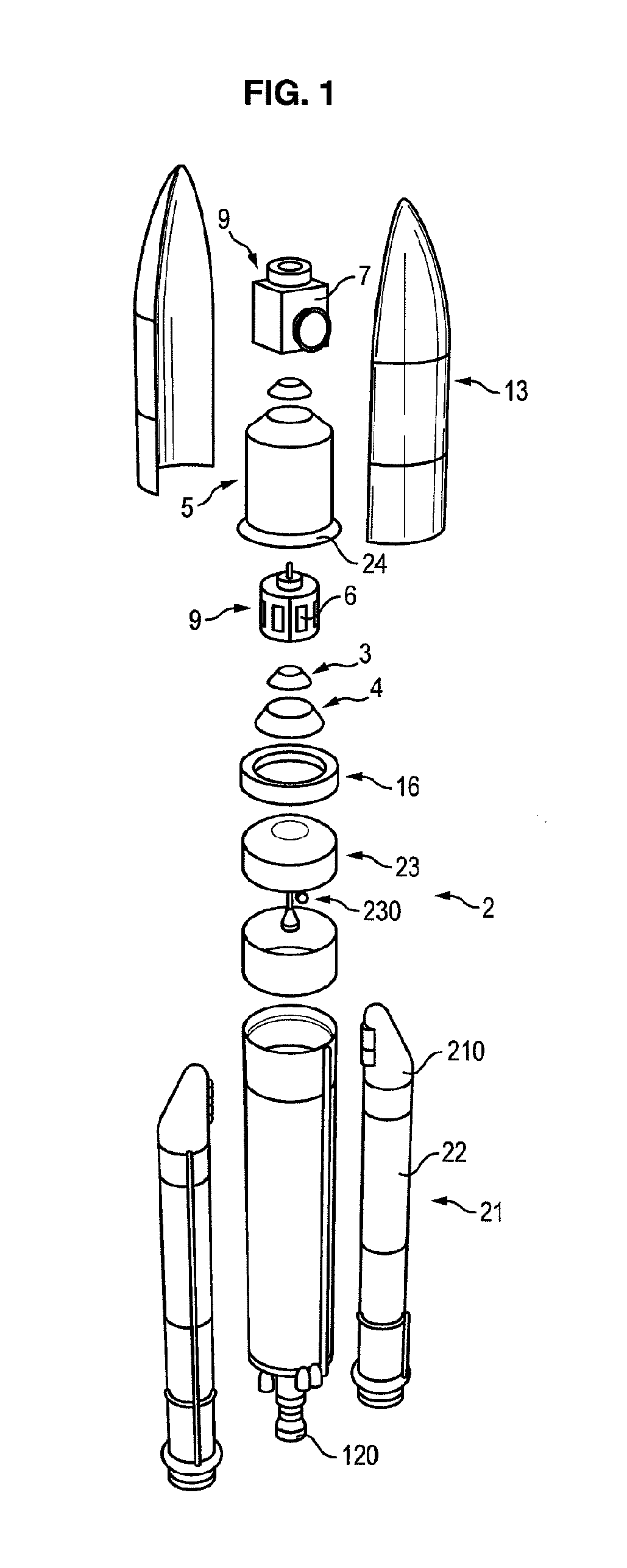
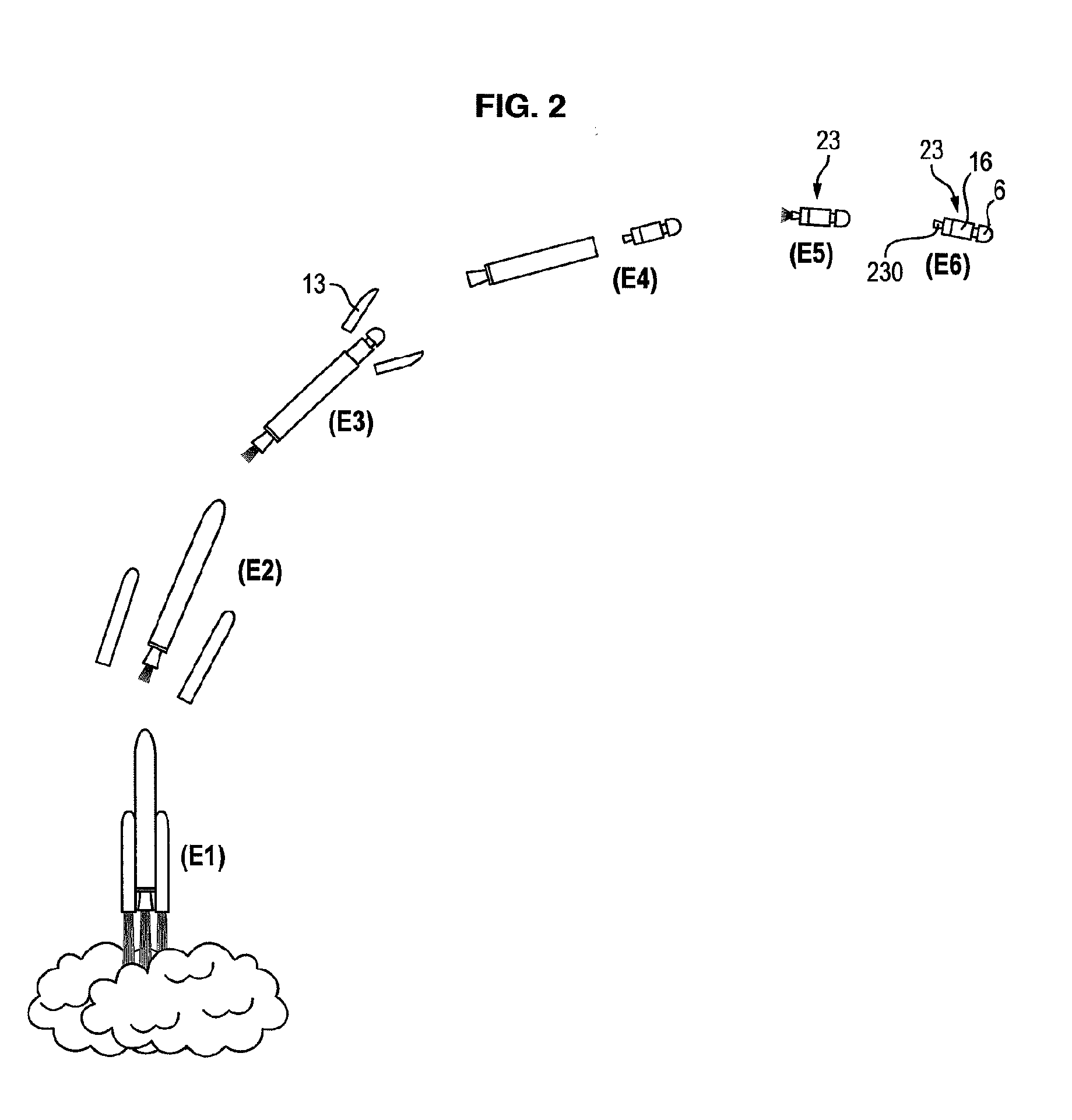
[0045]The bay 1 is intended to be housed in a launch vehicle 2.

[0046]Compared with the launch vehicle 2 presented with reference to the prior art, the bay 1 is additional and is housed in the launch vehicle 2 at least temporarily, at the level of an equipment bay 16. No adapting of the launch vehicle 2 is required to house the bay 1. The bay 1 therefore has dimensions adapted for housing thereof inside the launch vehicle 2: typically a diameter of a few metres and height in the order of one metre. Aside from this difference, the launch vehicle 2 transporting the bay 1 at least temporarily conforms to the presentation given in the introductory part of the present application and it will not be further described for reasons for clarity and conciseness.

[0047]As shown in FIGS. 3 and 4, the bay 1 is of substantially flattened cylindrical shape and chiefly comprises a peri...


PUM


Abstract

This invention relates to a propulsion bay to be transported, at least temporarily, in a space launch vehicle and comprising an adapter that co-operates with at least one system located, at least temporarily, on board the bay, said system comprising an electrical power supply. The bay is characterized in that it also comprises at least one electric space propulsion engine that can be powered by the power supply of the system.

Description

DESCRIPTION[0001]The present invention concerns a propulsion bay intended to be transported, at least temporarily, in a space launch vehicle, comprising an adapter that cooperates with at least one system loaded at least temporarily on board the bay, the system comprising an electric power supply.STATE OF THE ART[0002]As shown in FIG. 1, space launch vehicles 2 are known for the transporting at least temporarily of at least one equipment bay 16 on which equipment 6 or 7 and propulsion means 230 are secured.[0003]The equipment bay 16 comprises an adapter 3, 4 that cooperates with at least the system 6 loaded on board the bay 16 at least temporarily. The system 6 loaded on board generally forms an artificial satellite.[0004]To send the system 6 into space and place it on orbit, the launch vehicle 2 conventionally comprises several stages, namely:[0005]a lift-off stage 21 comprising boosters 210, with known solid-fuelled propulsion;[0006]a lower cryogenic stage 22 comprising an engine ...

Claims


Application Information

Patent Timeline
IPC IPC(8): B64G1/42B64G1/44B64G1/64B64G1/40
CPCB64G1/40B64G1/42B64G1/422B64G1/443B64G1/64B64G1/503B64G1/405B64G1/007B64G1/242B64G1/428B64G1/641B64G1/406B64G1/44B64G1/2427B64G1/415
Inventor BULTEL, PASCAL
Owner CENT NAT DETUD SPATIALES C N E S
Why Eureka
Try Eureka