
Headlight control device

a control device and headlight technology, applied in the direction of lighting and heating equipment, instruments, transportation and packaging, etc., can solve problems such as glar

Active Publication Date: 2015-01-01
SUBARU CORP
View PDF6 Cites 16 Cited by
  • Summary
  • Abstract
  • Description
  • Claims
  • Application Information

AI Technical Summary

Benefits of technology

The present invention aims to provide a headlight control device that can distinguish the reflected light of the vehicle's headlight from other light sources. This helps prevent glare caused by direct illumination of the vehicle ahead with a high beam. Additionally, it improves the identification of a light source of a vehicle headlight with high precision, which is important for performing auto high beam control.

Problems solved by technology

When a light source of a vehicle ahead is falsely recognized as reflected light of the headlight of the vehicle, glare may be caused by direct illumination of the vehicle ahead with a high beam.

Method used


Image

  • Headlight control device
  • Headlight control device
  • Headlight control device

Examples


example

[0022]An example of a headlight control device according to the present invention will be described below.

[0023]The headlight control device of the example is provided at the front of a body of an automobile such as, for instance, a passenger car to control a headlight for illumination of a predetermined region ahead of the vehicle.

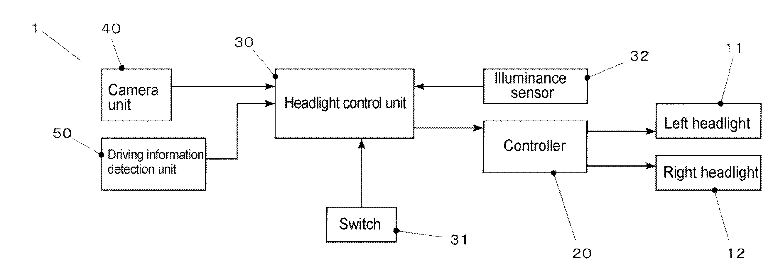
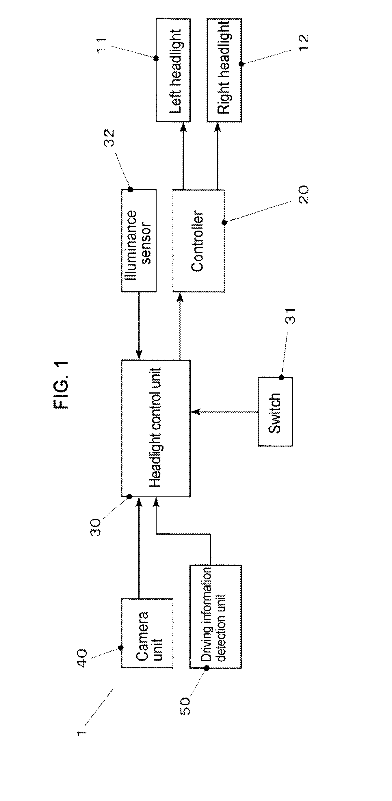
[0024]FIG. 1 is a block diagram illustrating the configuration of the headlight control device of the example.

[0025]As illustrated in FIG. 1, a headlight control device 1 includes a left headlight 11, a right headlight 12, a controller 20, a headlight control unit 30, a camera unit 40, a driving information detection unit 50, and the like.

[0026]The left headlight 11 and the right headlight 12 are provided respectively on left and right at the front of the body.

[0027]For the left headlight 11 and the right headlight 12, high beam (driving beam) for illumination up to, for instance, 100 m or more ahead of the vehicle and low beam (passing beam) for illumina...

modified example

[0091]The present invention is not limited to the example described above. Various modifications and changes are possible and within the technical scope of the present invention.

[0092](1) The configuration of the headlight control device or the headlight is not limited to those of the example described above and may be changed appropriately.

[0093]For instance, although the auto high beam control performs switching between high beam and low beam in the example, this is not limiting. For instance, light distribution patterns for high beam may be switched according to the recognition result for a light source ahead with a headlight having a plurality of light distribution patterns for high beam.

[0094](2) Although an LED light source is used as the light source of the headlight in the example, this is not limiting. The light source may be any type of light source, as long as blinking is possible at a high rate to an extent that a problem of flicker rarely arises upon visual contact with...


PUM


Abstract

A headlight control device automatically switches a light distribution pattern of a headlight for illumination ahead of a vehicle. The headlight control device including an imager that sequentially takes images of a view ahead of the vehicle in a predetermined frame rate, an another-vehicle recognizer that recognizes a light source of another vehicle from each of the images sequentially taken by the imager, a light distribution controller that switches the light distribution pattern according to a recognition result of the another-vehicle recognizer, and a signal provider that provides a signal to illumination light of the headlight by causing the luminance of the headlight to change in a predetermined cycle. The another-vehicle recognizer recognizes, as reflected light of the headlight of the vehicle, a light source which is present within the image and of which luminance change is substantially similar to a luminance change of the signal.

Description

CROSS-REFERENCE TO RELATED APPLICATIONS[0001]The present application claims priority from Japanese Patent Application No. 2013-133750 filed on Jun. 26, 2013, the entire contents of which are hereby incorporated by reference.BACKGROUND[0002]1. Technical Field[0003]The present invention relates to a headlight control device with which a situation ahead of a vehicle is detected and a light distribution pattern is automatically switched, and particularly relates to a headlight control device capable of identifying reflected light of a headlight of the vehicle from other light sources.[0004]2. Related Art[0005]A headlight of a vehicle such as an automobile is generally capable of switching between driving beam (high beam) and passing beam (low beam) or capable of turning off a driving beam independently from a passing beam.[0006]In recent years, there have been proposals for a function (auto high beam function) of recognizing a situation ahead of a vehicle with a camera, radar, or the li...

Claims


Application Information

Patent Timeline
Patent Type & Authority Applications(United States)
IPC IPC(8): B60Q1/08
CPCB60Q1/085G06K9/00B60Q1/143B60Q2300/144B60Q2300/314B60Q2300/3321B60Q2300/42F21S41/00G06V20/584B60Q1/0023B60Q2300/41B60Q1/04B60Q1/08B60Q2300/054B60Q1/1423
Inventor HAYAKAWA, KAZUHIROAOKI, YUTO
Owner SUBARU CORP
Learn More