
Scalable multi-layer 2d-mesh routers

a router and multi-layer technology, applied in the field of routing, can solve the problems of not being scalable, not having a scalable solution, and fundamentally limited router chip frequency,

Inactive Publication Date: 2015-01-01
INTEL CORP
View PDF9 Cites 7 Cited by
  • Summary
  • Abstract
  • Description
  • Claims
  • Application Information

AI Technical Summary

Benefits of technology

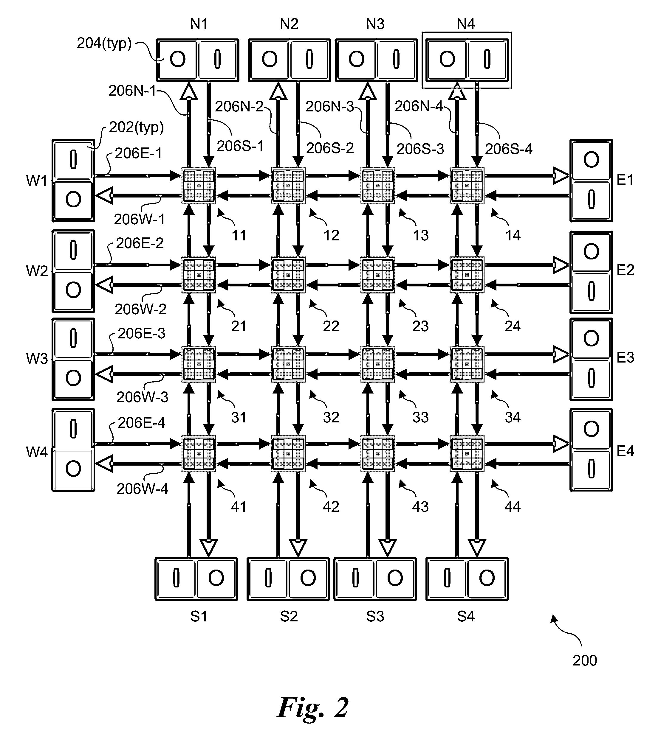
The invention is about a new multi-layer two-dimensional (2D)-mesh router architecture that solves problems with traditional router chips. The new architecture has a higher radix (the number of inputs and outputs) and a more symmetrical distribution of traffic, which helps to deliver sufficient bandwidth in many situations. It also reduces the concentration of traffic on the central part of the chip, improving performance. The new architecture uses a combination of topology and routing to optimize bandwidth and minimize latency. The invention includes a method for configuring a 2D router mesh with bi-directional data paths and a method for selecting the optimal route between input and output nodes. Overall, the invention provides a more efficient and effective way to build high-radix, high-bandwidth routers.

Problems solved by technology

First, chip frequencies for routers are fundamentally limited by resistive-capacitive (RC) / wire delay—after all, there is some minimum amount of time required to get signals from one side of a chip to the other.
However, this is a not a scalable solution since the quanta of data that is moved in a router chip is not large, or at least does not increase with increasing data rates.
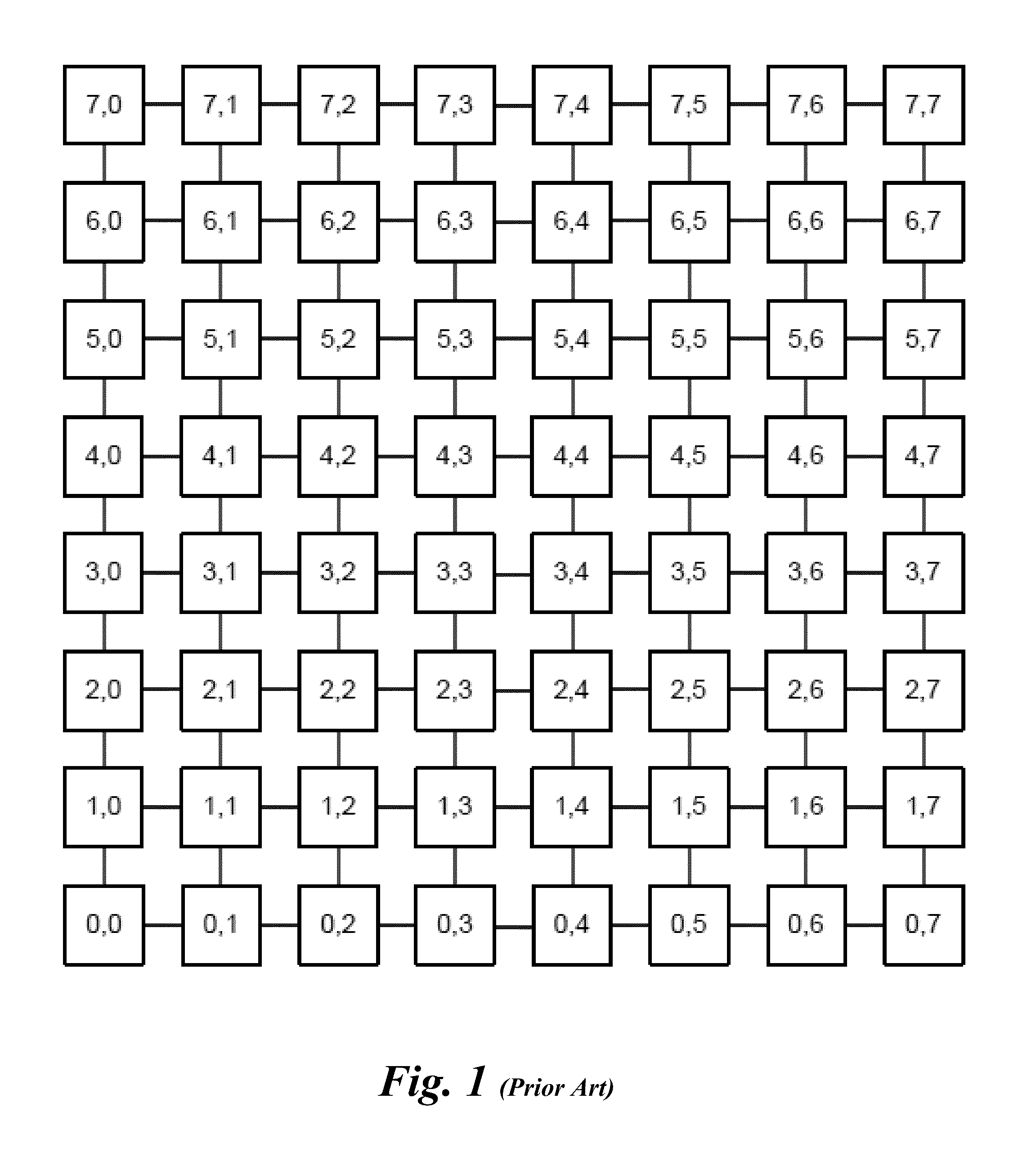
However, the concentration of traffic is very uneven, drastically overburdening the central part of the chip, while the perimeter is comparatively underutilized.
This asymmetry of bandwidth usage compromises the 2D-mesh's ability to deliver sufficient bandwidth in many situations.
This is expensive in terms of routing area and energy, and does not scale well.
This approach is also inefficient.

Method used


Image

  • Scalable multi-layer 2d-mesh routers
  • Scalable multi-layer 2d-mesh routers
  • Scalable multi-layer 2d-mesh routers

Examples


Embodiment Construction

[0021]Embodiments of architectures, apparatus and systems for implementing scalable multi-layer 2D-mesh routers are described herein. In the following description, numerous specific details are set forth to provide a thorough understanding of embodiments of the invention. One skilled in the relevant art will recognize, however, that the invention can be practiced without one or more of the specific details, or with other methods, components, materials, etc. In other instances, well-known structures, materials, or operations are not shown or described in detail to avoid obscuring aspects of the invention.

[0022]Reference throughout this specification to “one embodiment” or “an embodiment” means that a particular feature, structure, or characteristic described in connection with the embodiment is included in at least one embodiment of the present invention. Thus, the appearances of the phrases “in one embodiment” or “in an embodiment” in various places throughout this specification are...


PUM


Abstract

Architectures, apparatus and systems employing scalable multi-layer 2D-mesh routers. A 2D router mesh comprises bi-direction pairs of linked paths coupled between pairs of IO interfaces and configured in a plurality of rows and columns forming a 2D mesh. Router nodes are located at the intersections of the rows and columns, and are configured to forward data units between IO inputs and outputs coupled to the mesh at its edges through use of shortest path routes defined by agents at the IO interfaces. Multiple instances of the 2D meshes may be employed to support bandwidth scaling of the router architecture. One implementation of a multi-layer 2D mesh is built using a standard tile that is tessellated to form a 2D array of standard tiles, with each 2D mesh layer offset and overlaid relative to the other 2D mesh layers. IO interfaces are then coupled to the multi-layer 2D mesh via muxes / demuxes and / or crossbar interconnects.

Description

FIELD OF THE INVENTION[0001]The field of invention relates generally to routing and, more specifically but not exclusively relates to a multi-layer two-dimensional (2D)-mesh router architecture.BACKGROUND INFORMATION[0002]Router chips have historically been challenged to handle progressively higher data rates and at higher radix (i.e., the number of inputs and outputs) for at least two reasons. First, chip frequencies for routers are fundamentally limited by resistive-capacitive (RC) / wire delay—after all, there is some minimum amount of time required to get signals from one side of a chip to the other. Increasing the data rate, under a fixed frequency, amounts to employing wider internal busses. However, this is a not a scalable solution since the quanta of data that is moved in a router chip is not large, or at least does not increase with increasing data rates. Second, it is preferable to have a router that is high-radix: it is preferable to have many narrow channels on a router r...

Claims


Application Information

Patent Timeline
Patent Type & Authority Applications(United States)
IPC IPC(8): H04L12/24H04L12/933H04L12/733H04L45/122
CPCH04L49/15H04L49/101H04L45/122H04L41/12H04L45/12H04L49/25
Inventor HASENPLAUGH, WILLIAM C.FOSSUM, TRYGGVELEONARD, JUDSON S.
Owner INTEL CORP
Learn More