
rasp

Active Publication Date: 2015-01-01
AOD HLDG
View PDF4 Cites 8 Cited by
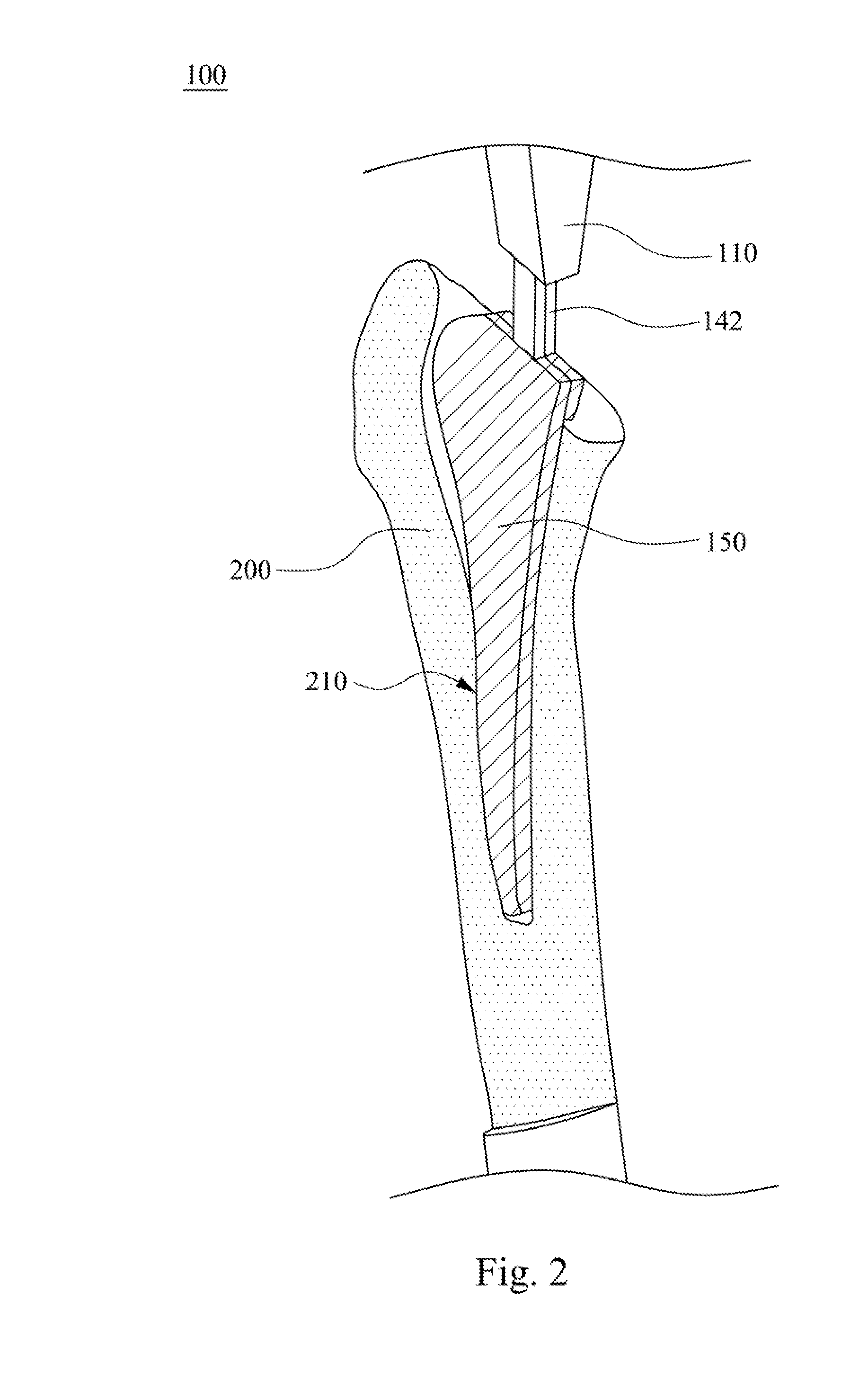
  • Summary
  • Abstract
  • Description
  • Claims
  • Application Information

AI Technical Summary

Benefits of technology

The patent text describes a technical solution for shaping bones that results in a net force that is nearly zero. This allows for better control for the surgeon during the shaping process.

Problems solved by technology

Inventions in the prior art also experience a number of problems.
Some of these designs utilize many gears and other moving parts which can be prone to fail.
In addition, the rapid reciprocating action of these power tools can affect the precision of the instrument during operation.
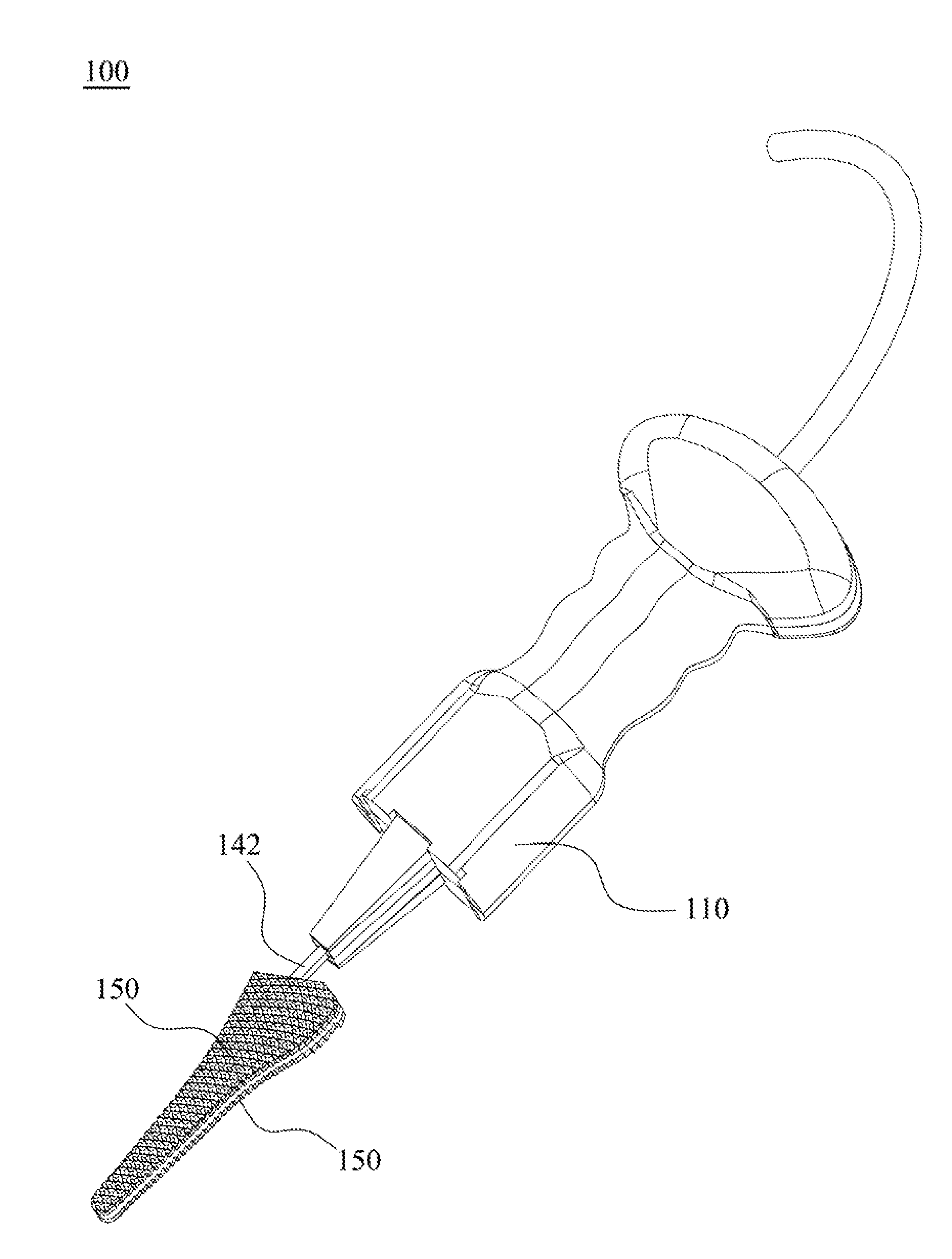
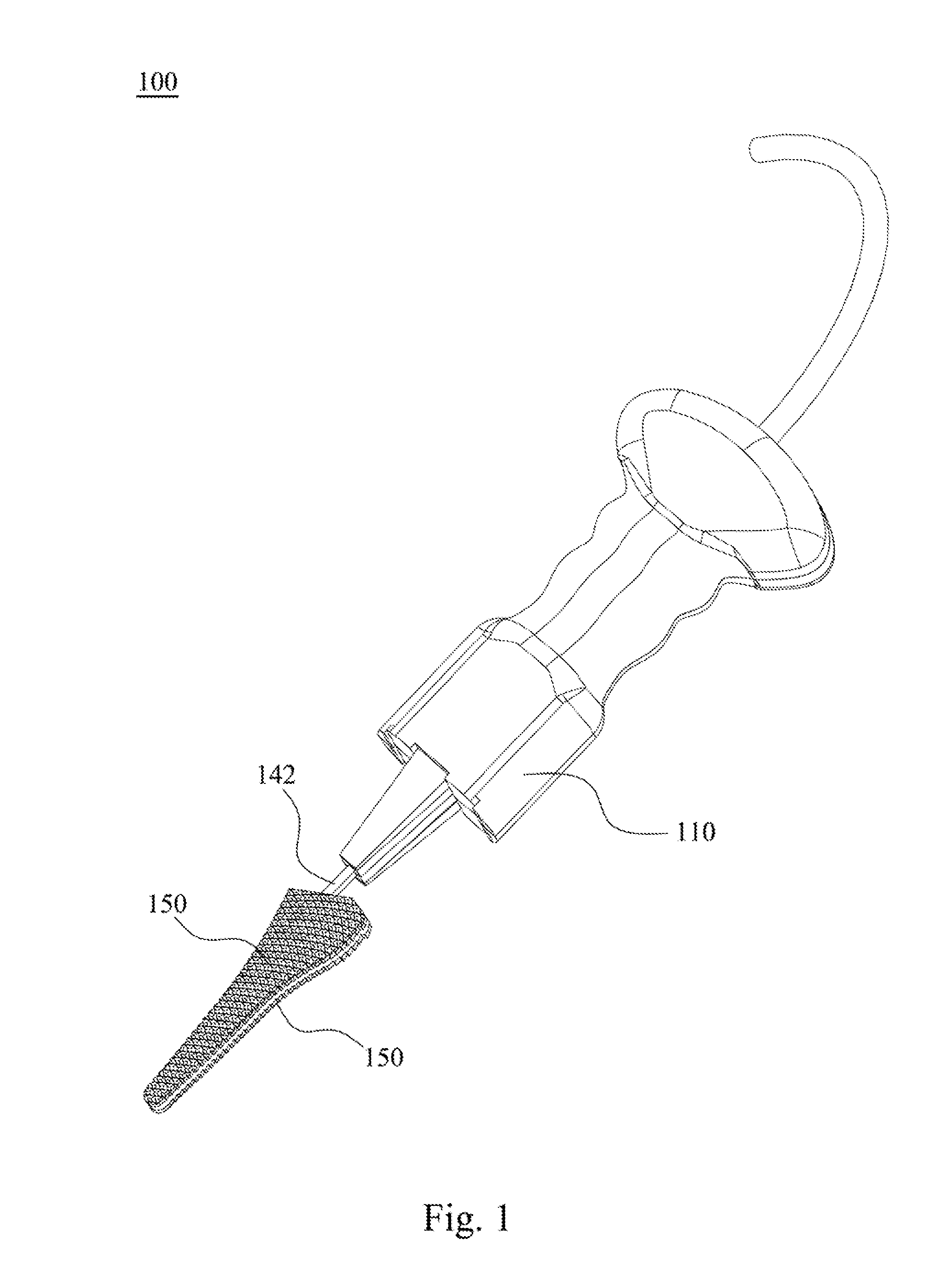
(1) In the embodiments of the present disclosure, the linkage units are driven by the first gear assembly to move along the channel in a reciprocating manner. Therefore, the two blades respectively connected to the linkage units are driven to move in a reciprocating manner as well. In this way, during an operation, the forces acting on the bone by each of the two blades cancel out with each other, such that the net resultant force acting on the bone by the rasp is zero. As a result, the surgeon can have a better control over the use of the rasp. Consequently, the safety of operation is obviously increased.
(2) In the embodiments of the present disclosure, there are only a small number of moving parts involved. Thus, the chance that any of the moving parts gets failed is low, and the maintenance time and cost of the rasp is significantly decreased.
(3) In the embodiments of the present disclosure, the output gear has a second pitch center diameter smaller than the first pitch center diameters of the first gear and the second gear. Therefore, the forces acting on the linkage units respectively by the first gear and the second gear are increased in magnitude while decreased in speed relative to the output gear. As a result, the surgeon can have a better control over the use of the rasp. Consequently, the safety of operation is obviously increased.
(4) In the embodiments of the present disclosure, the linkage units slidably pass through the channel. Thus, the reciprocating movements of the linkage units along the sliding direction can be simply guided by the channel. In addition, each of the blades has a plurality of grooves parallel to each other, and the grooves of one of the blades are slidably engaged with the grooves of another one of the blades. As a result, the risk that the two blades have lateral movements with each other is safely avoided.

Method used


Image

  • rasp
  • rasp
  • rasp

Examples


Embodiment Construction

[0040]Drawings will be used below to disclose a plurality of embodiments of the present disclosure. For the sake of clear illustration, many practical details will be explained together in the description below. However, it is appreciated that the practical details should not be used to limit the claimed scope. In other words, in some embodiments of the present disclosure, the practical details are not essential. Moreover, for the sake of drawing simplification, some customary structures and elements in the drawings will be schematically shown in a simplified way. Wherever possible, the same reference numbers are used in the drawings and the description to refer to the same or like parts.

[0041]Unless otherwise defined, all terms (including technical and scientific terms) used herein have the same meaning as commonly understood by one of ordinary skill in the art to which this disclosure belongs. It will be further understood that terms, such as those defined in commonly used diction...


PUM


Abstract

A rasp for shaping a bone is provided. The rasp includes a housing, a driving mechanism, a first gear assembly, two linkage units and two blades. The housing has a channel along a first axis. The driving mechanism has an output gear rotating about the first axis. The first gear assembly rotates about a second axis and is driven by the output gear. The first gear assembly has a first and a second rotation surfaces. A first and a second connection points are respectively located on the first and the second rotation surfaces. The linkage units slidably pass through the channel. The first end of each of the linkage units is pivotally connected to the corresponding connection point, such that the second ends move along the first axis in a reciprocating manner. The blades are respectively and detachably connected to the second ends.

Description

RELATED APPLICATIONS[0001]This application claims priority to U.S. Provisional Application No. 61 / 839,613, filed Jun. 26, 2013, which is herein incorporated by reference.BACKGROUND[0002]1. Technical Field[0003]The present disclosure relates to rasps. More particularly, the present disclosure relates to rasps for shaping bones for receiving a prosthesis.[0004]2. Description of Related Art[0005]Prior to inserting a prosthesis in a bone, and in particular a prosthesis in the top end of a femur, the surgeon must prepare the medullary cavity of the bone so as to give it a shape which is complementary to the shape of the prosthesis. This is done by using a rasp which includes a handle for gripping and a toothed blade whose shape corresponds to the shape of the prosthesis. The teeth on the blade are sharp, thereby enabling them to scrape away the surrounding spongy bone, much like a file.[0006]Surgical ablating tools for use in the resection of bone and tissue during surgical procedures ar...

Claims


Application Information

Patent Timeline
IPC IPC(8): A61B17/16
CPCA61B17/1659A61B17/1668A61B17/1624A61B17/16A61B17/1622A61B17/1628A61B17/1675A61B17/1684
Inventor FERRO, THOMAS D.PHILLIPS, JOELEE, DONALDPARK, JOHNFERRO, AUSTIN T.
Owner AOD HLDG
Learn More