Shift position detecting device

a technology of shifting position and detection device, which is applied in the direction of mechanical equipment, digital data processing details, instruments, etc., can solve the problems of easy perception of the influence of friction, affecting the operation of the operator, and causing friction, so as to achieve the effect of reducing the influence of friction

Active Publication Date: 2015-01-01
HONDA MOTOR CO LTD
View PDF5 Cites 4 Cited by
  • Summary
  • Abstract
  • Description
  • Claims
  • Application Information

AI Technical Summary

Benefits of technology

[0007]The invention has been made in view of such circumstances, and it is an object of an embodiment of the present invention to provide a shift position detecting device that allows a rider to have an operational feeling with no discomfort by alleviating a change in friction at the time of performing a shift operational to a neutral position.

Problems solved by technology

However, when timings at which the plurality of switches come into contact with the projecting portions are equal, a friction caused by the contact of the switch to the projecting portion occurs simultaneously with respect to the plurality of the switches.
Thus, the movement of the shift drum is liable to be obstructed.
Thus, the operator is liable to easily perceive the influence of a friction.

Method used


Image

  • Shift position detecting device
  • Shift position detecting device
  • Shift position detecting device

Examples


Embodiment Construction

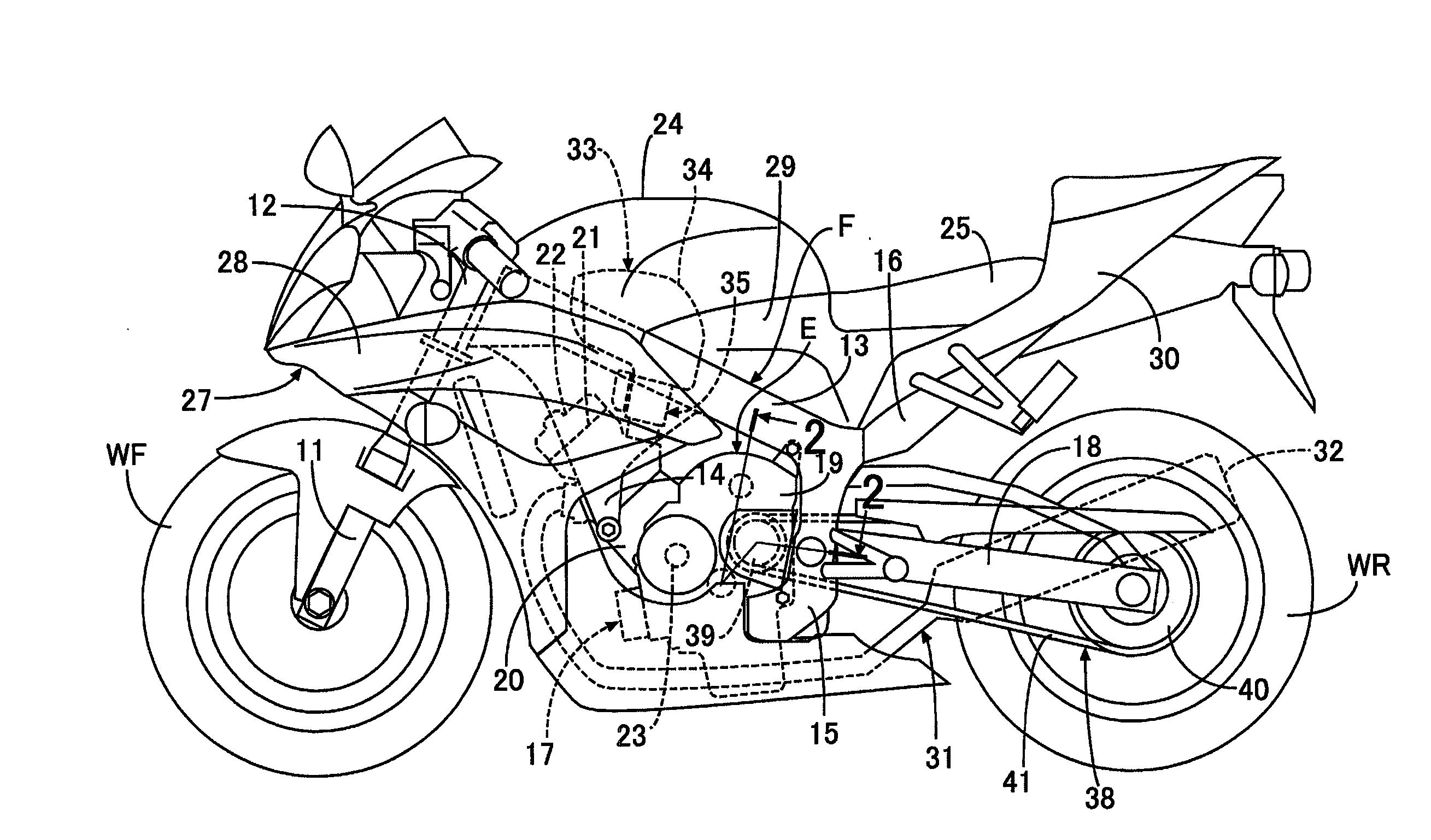
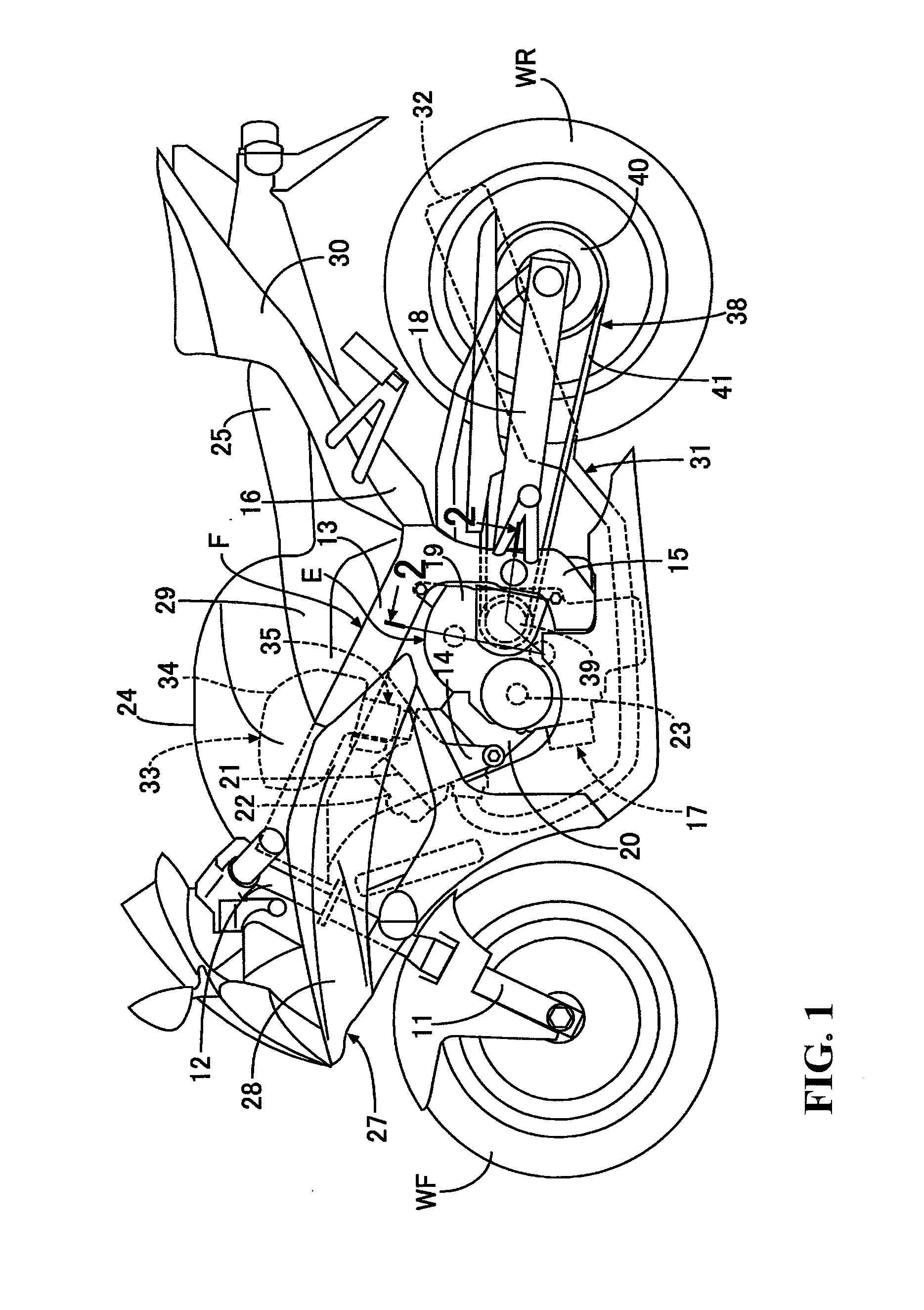
[0033]Hereinafter, an embodiment of the invention is explained by reference to FIG. 1 to FIG. 13. As illustrated in FIG. 1, a vehicle body frame F of a motorcycle includes a head pipe 12 that steerably supports a front fork 11 that pivotally supports a front wheel WF; a main frame 13 that extends rearwardly and downwardly from the head pipe 12; an engine hanger 14 that extends downwardly from a front portion of the main frame 13; a pivot frame 15 that extends downwardly from a rear portion of the main frame 13; and a seat rail 16 that extends rearwardly and upwardly from the rear portion of the main frame 13.

[0034]An engine body 17 of an engine E that is arranged below the main frame 13 is supported on the rear portion of the main frame 13, a lower portion of the engine hanger 14 and a lower portion of the pivot frame 15 of the vehicle body frame F. A rear wheel WR driven by power that the engine E generates is pivotally supported on a rear end portion of a swing arm 18. A front end...


PUM


Abstract

A shift position detecting device where a shift position determining member is provided for determining a shift position based on a combination of switching modes of three switches corresponding to at least one of a plurality of projection rows each having a plurality of projection portions in a one-by-one basis, and “1, 1, 1” indicative of an ON state of each switch is allocated as a detection logic at a neutral position arranged between a first speed position and a second speed position, wherein a change in friction at the time of a shift operational to the neutral position is alleviated thus giving an operational feeling with no discomfort to a rider. Two projection rows that are objects to be detected by two specified switches among the three switches are formed so as to change switching modes of the specified switches from an OFF state to an ON state.

Description

CROSS-REFERENCE TO RELATED APPLICATIONS[0001]The present application claims priority under 35 USC 119 to Japanese Patent Application No. 2013-136929 filed Jun. 28, 2013 the entire contents of which are hereby incorporated by reference.BACKGROUND OF THE INVENTION[0002]1. Field of the Invention[0003]The present invention relates to a shift position detecting device that includes a plurality of projection rows each of which includes projecting portions arranged at a plurality of places in a spaced-apart manner in the circumferential direction of a shift drum constituting a part of a multi-stage transmission having gear trains of a plurality of shift stages that are selectively establishable, and are mounted on the shift drum. Three switches that are fixedly arranged at least one by one corresponding to the plurality of projection rows such that a switching mode is changed from an OFF state to an ON state by being brought into contact with the projecting portions. A shift position deter...

Claims


Application Information

Patent Timeline
Patent Type & Authority Applications(United States)
IPC IPC(8): F16H61/02
CPCF16H61/0213F16H63/18F16H59/70
Inventor HOTEI, TAKASHITETSUKA, TAKASHIARAI, DAICHIBA, ATSUSHI
Owner HONDA MOTOR CO LTD
Why Eureka
Try Eureka