Method and apparatus for continued retirement during commit of a speculative region of code

Active Publication Date: 2015-01-01
INTEL CORP
View PDF25 Cites 10 Cited by
  • Summary
  • Abstract
  • Description
  • Claims
  • Application Information

AI Technical Summary

Problems solved by technology

Delay in the retirement of the commit causes delay in the retirement of sub...

Method used


Image

  • Method and apparatus for continued retirement during commit of a speculative region of code
  • Method and apparatus for continued retirement during commit of a speculative region of code
  • Method and apparatus for continued retirement during commit of a speculative region of code

Examples


Embodiment Construction

[0026]In the following description, for the purposes of explanation, numerous specific details are set forth in order to provide a thorough understanding of the embodiments of the invention described below. It will be apparent, however, to one skilled in the art that the embodiments of the invention may be practiced without some of these specific details. In other instances, well-known structures and devices are shown in block diagram form to avoid obscuring the underlying principles of the embodiments of the invention.

Exemplary Processor Architectures and Data Types

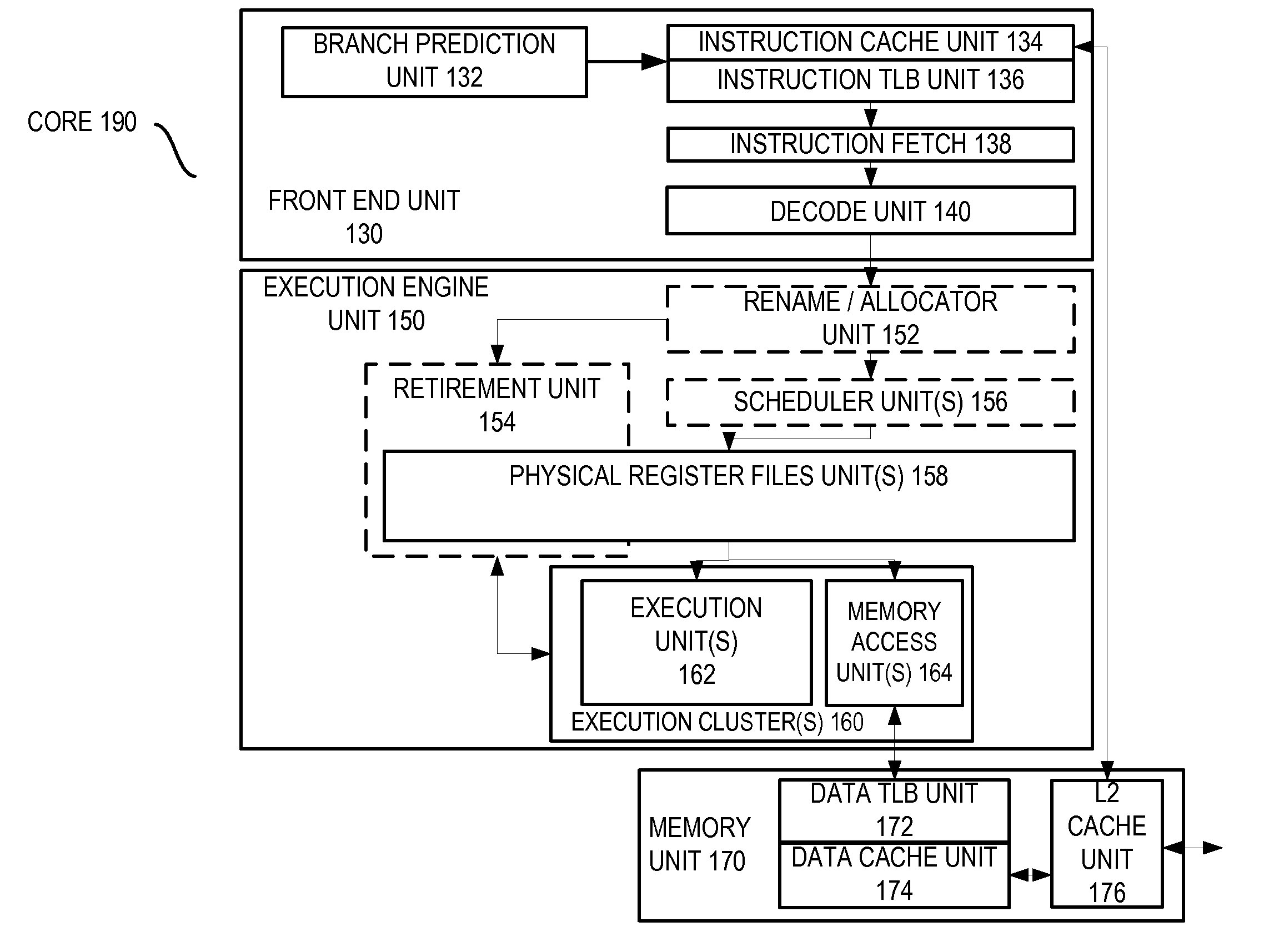
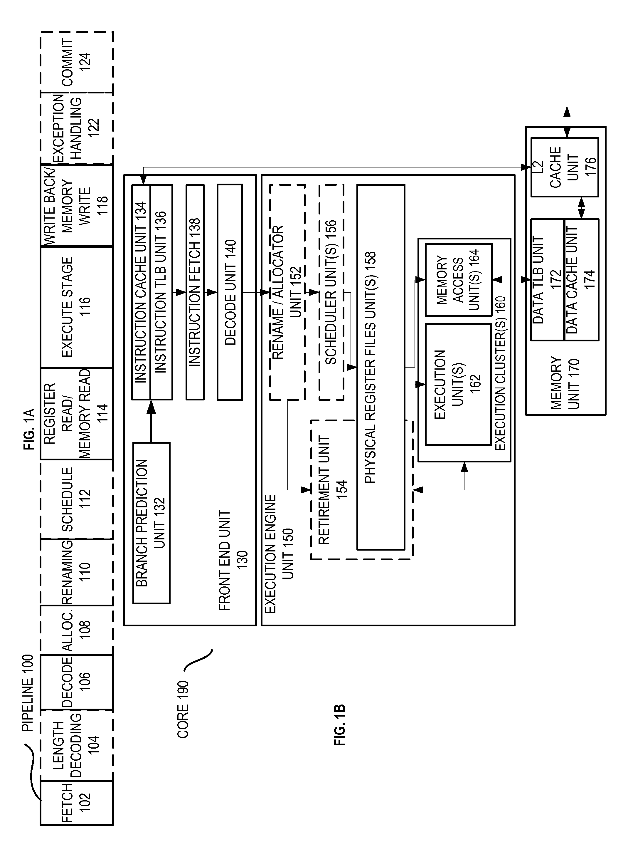
[0027]FIG. 1A is a block diagram illustrating both an exemplary in-order pipeline and an exemplary register renaming, out-of-order issue / execution pipeline according to embodiments of the invention. FIG. 1B is a block diagram illustrating both an exemplary embodiment of an in-order architecture core and an exemplary register renaming, out-of-order issue / execution architecture core to be included in a processor according ...


PUM


Abstract

A processor, system, and method are described for continued retirement of operations during a commit of a speculative region of program code. For example, one embodiment of a method comprises the operations of identifying a plurality of transactional memory regions in program code, including a first transactional memory region; and retiring one or more of a plurality of operations which follow the first transactional memory region even when a commit operation associated with the first transactional memory region is waiting to complete.

Description

BACKGROUND[0001]1. Field of the Invention[0002]This invention relates generally to the field of computer processors and software. More particularly, the invention relates to a method and apparatus for continued retirement during commit of a speculative region of code.[0003]2. Description of the Related Art[0004]In prior processor architectures, the reorder buffer (ROB) was forced to stall retirement when a region commit uop was the oldest until the memory system (MEU) was prepared to commit values altered in the region. This process caused the out-of-order speculation mechanism to get “backed up” while waiting for the MEU. That is, at the time the commit operation is at the head of the ROB and ready to retire, its retirement is held back, thus preventing the ROB from retiring and speculating deeper into code subsequent to the region. Delay in the retirement of the commit causes delay in the retirement of subsequent uops, which delays releasing resources causing yet other sources of ...

Claims


Application Information

Patent Timeline
IPC IPC(8): G06F9/46
CPCG06F9/467G06F9/3842G06F9/3863G06F9/466G06F9/384G06F9/528G06F9/3836G06F9/3861G06F9/3858
Inventor RAJWAR, RAVIMERTEN, MATTHEW C.WANG, CHRISTINE E.KADGI, VIJAYKUMAR B.PARTHASARATHY, RAJESH S.
Owner INTEL CORP
Why Eureka
Try Eureka