Plant potting apparatus and method

Inactive Publication Date: 2015-01-08
DELP II STEVEN P
View PDF12 Cites 15 Cited by
  • Summary
  • Abstract
  • Description
  • Claims
  • Application Information

AI Technical Summary

Benefits of technology

[0004]The present invention provides a decorative plant stand that allows the caretaker to remove collected water from the plant without having to lift or remove the plant from the floor or the plant stand. In the present invention, the water collection tray is placed below the plant stand, which allows for easier emptying of the collection tray without having to move or lift the plant from the floor or the

Problems solved by technology

On their own, they weigh a significant amount but they are also often planted into heavy pots.
They are thus cumbersome to move.
When overwatered, often times the pot leaks water through an ope

Method used


Image

  • Plant potting apparatus and method
  • Plant potting apparatus and method
  • Plant potting apparatus and method

Examples


Example

[0013]While the invention is amenable to various modifications and alternative forms, specifics thereof are shown by way of example in the drawings and described in detail herein. It should be understood, however, that the intention is not to limit the invention to the particular embodiments described. On the contrary, the intention is to cover all modifications, equivalents, and alternatives falling within the spirit and scope of the invention.

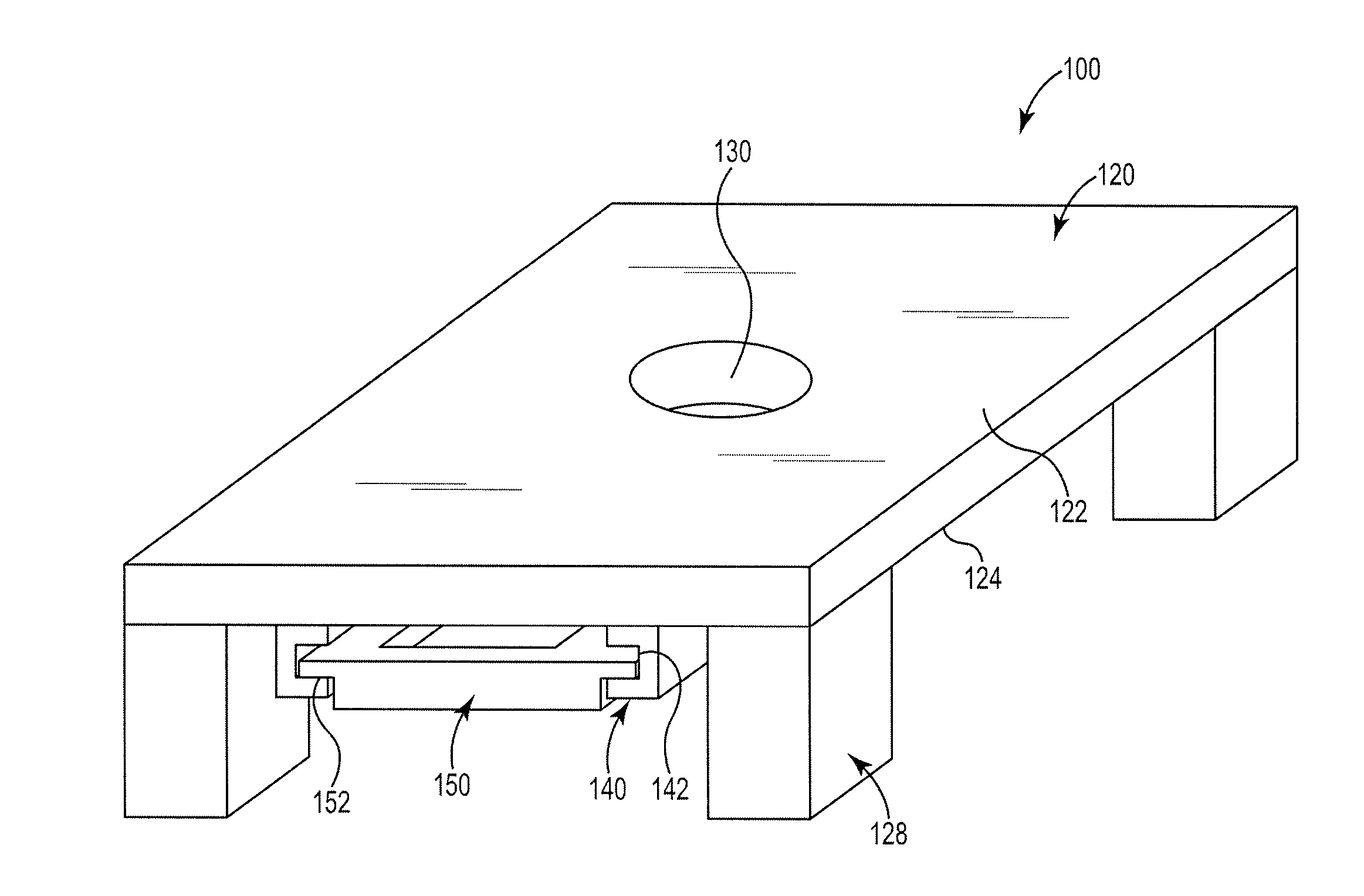
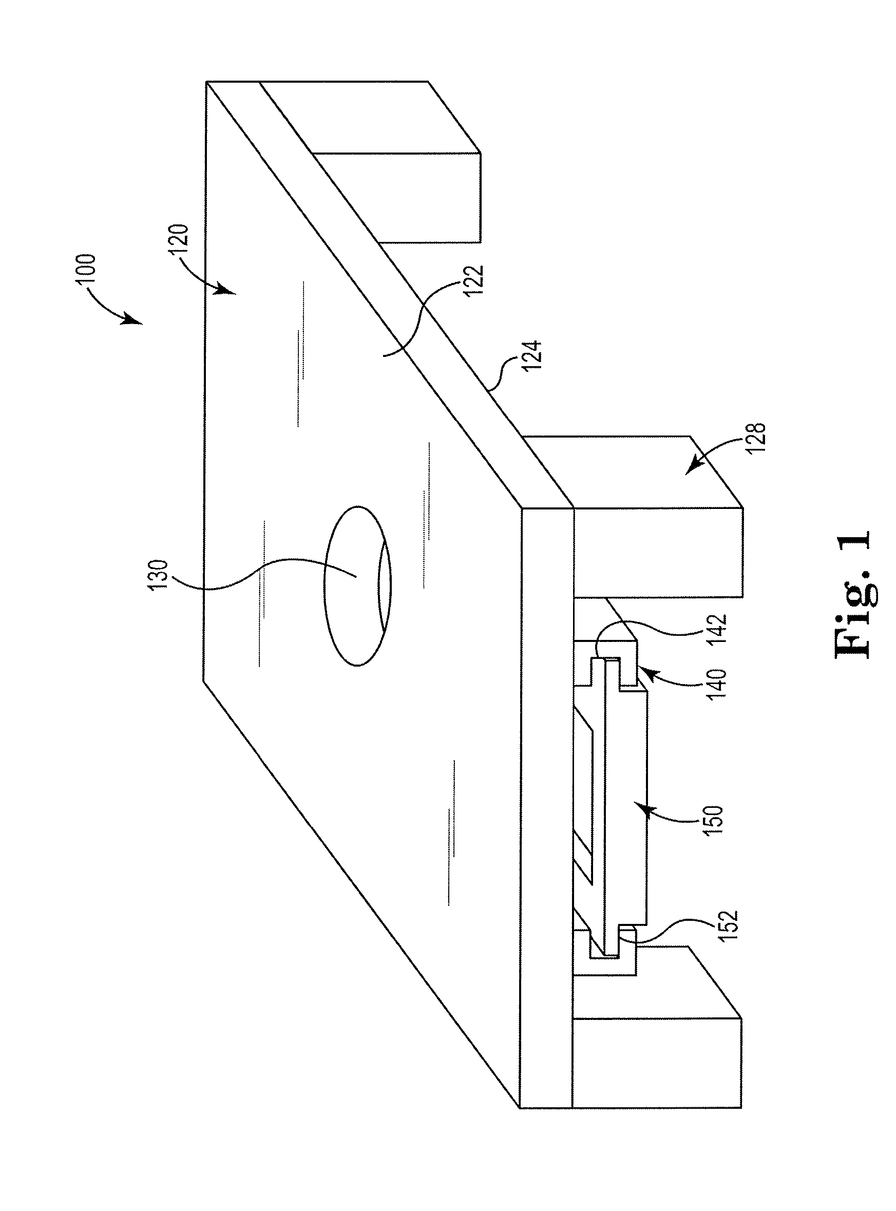
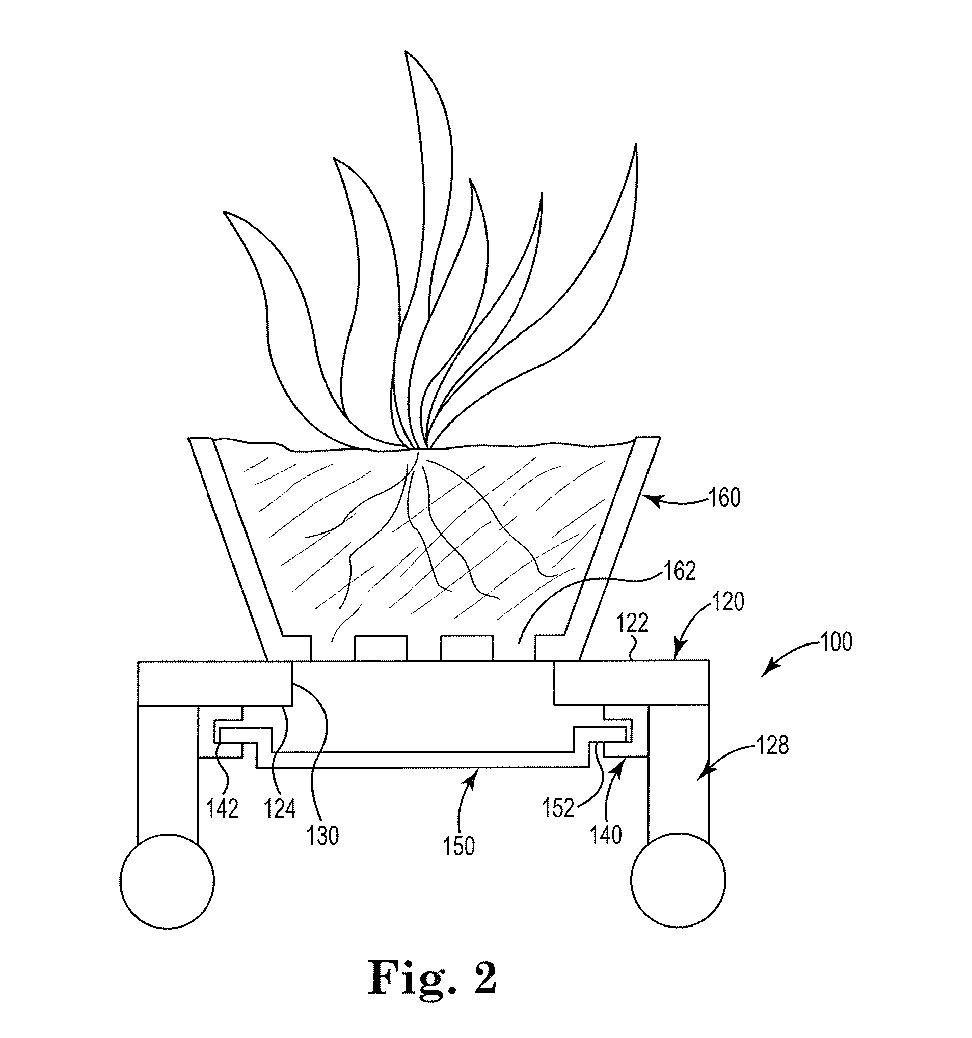
[0014]FIGS. 1-2 shows embodiments of the plant stand for a potted plant of the present invention. The plant stand 100 comprises a platform 120, a plurality of legs 128 extending downwardly from the platform 120, a rail assembly 140 having a channel 142, and a removable tray 150 slidably disposed within the channel 142 of the rail assembly. The platform 120 has a top surface 122, a bottom surface 124 and a thickness therebetween. The legs 128 extend downwardly from the bottom surface 124 of the platform. In at least one embodiment, the legs 12...


PUM


Abstract

A decorative plant stand that allows the caretaker to remove collected water from the plant without having to lift or remove the plant from the floor or the plant stand. The plant stand comprises a platform comprising a top surface, a bottom surface, and a thickness therebetween, the platform at least one opening in the top surface extending through the entire thickness; a rail assembly positioned below the bottom surface of the platform and fixedly attached to the platform, the rail assembly comprising at least one channel; and a removable tray slidably disposed within the at least one channel, wherein any plant water and other debris that leak from the pot through the opening in the top surface are collected within the removable tray for disposal. A method for draining water from the plant, which is collected in the tray, is also provided.

Description

BACKGROUND[0001]This invention relates generally to a plant stand for use with large indoor plants. Large indoor plants are popular household decorative items. On their own, they weigh a significant amount but they are also often planted into heavy pots. They are thus cumbersome to move. When overwatered, often times the pot leaks water through an opening in the bottom of the pot. When such water leaks, it may stain the floor or stand upon which the potted plant rests.[0002]Several issued patents describe ways in which water may be drained from a pot. U.S. Pat. Pub. No. 2012 / 0255226 describes a plant holder placed into a water catching basin that has a drainage hole on the bottom surface of the basin. A rubber drainage plug is inserted into the drainage hole to prevent water collected in the basin from leaking out of the basin and onto the floor, furniture, or other base upon which the plant rests. To remove the collected water, the plant holder and water catching basin must be lift...

Claims


Application Information

Patent Timeline
IPC IPC(8): A01G9/12
CPCA01G9/12A01G9/04A01G9/143A01G31/02Y02P60/21Y02A40/25
Inventor DELP II, STEVEN P.
Owner DELP II STEVEN P
Why Eureka
Try Eureka