Standby flight display system

a display system and standby technology, applied in the field of aircraft, can solve the problems of adding weight and cost to the aircraft, consuming valuable space on an already crowded instrument panel, and using a separate and distinct standby flight display screen in the flight deck, so as to reduce the weight, cost and complexity of the aircra

Inactive Publication Date: 2015-01-15
GULFSTREAM AEROSPACE CORP
View PDF5 Cites 7 Cited by
  • Summary
  • Abstract
  • Description
  • Claims
  • Application Information

AI Technical Summary

Benefits of technology

[0006]Accordingly, it is desirable to provide a standby flight display system that enables an aircrew member to continue to have access to an aircraft's altitude, attitude, heading and airspeed information in the event of a failure of the aircraft's primary flight display system while also reducing the aircraft's weight, cost and complexity. Furthermore, other desirable features and characteristics will become apparent from the subsequent summary and detailed description and the appended claims, taken in conjunction with the accompanying drawings and the foregoing technical field and background.

Problems solved by technology

Furthermore, this redundant display system derives the altitude, attitude, heading, and airspeed information from a source(s) that differs from the source(s) used by the primary flight display system.
Thus, it is not sufficient to simply provide a redundant display screen in the flight deck.
The use of a separate and distinct standby flight display screen in the flight deck consumes valuable space on an already crowded instrument panel.
Further, the presence of a secondary monitor in the aircraft adds weight and cost to the aircraft.
In addition, there is added weight and cost arising out of the wires, cables, controllers, and other related equipment that is needed to support a separate standby flight display screen.
In summary, the use of a redundant display screen in a standby flight display system adds weight, cost, and complexity to the aircraft.

Method used


Image

  • Standby flight display system
  • Standby flight display system
  • Standby flight display system

Examples


Embodiment Construction

[0017]The following detailed description is merely exemplary in nature and is not intended to limit the invention or the application and uses of the invention. Furthermore, there is no intention to be bound by any theory presented in the preceding background or the following detailed description.

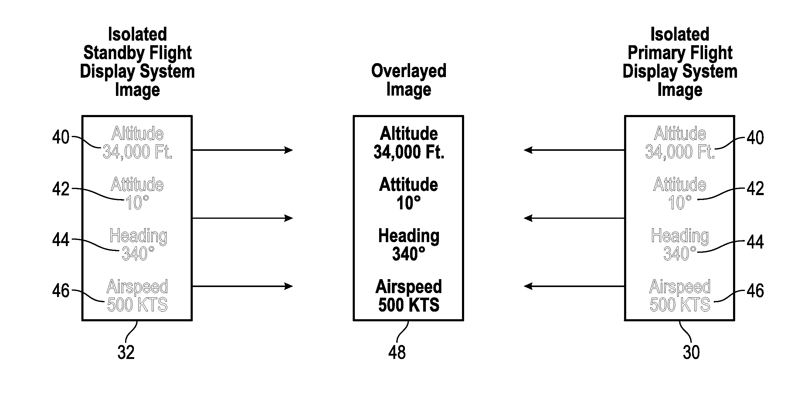
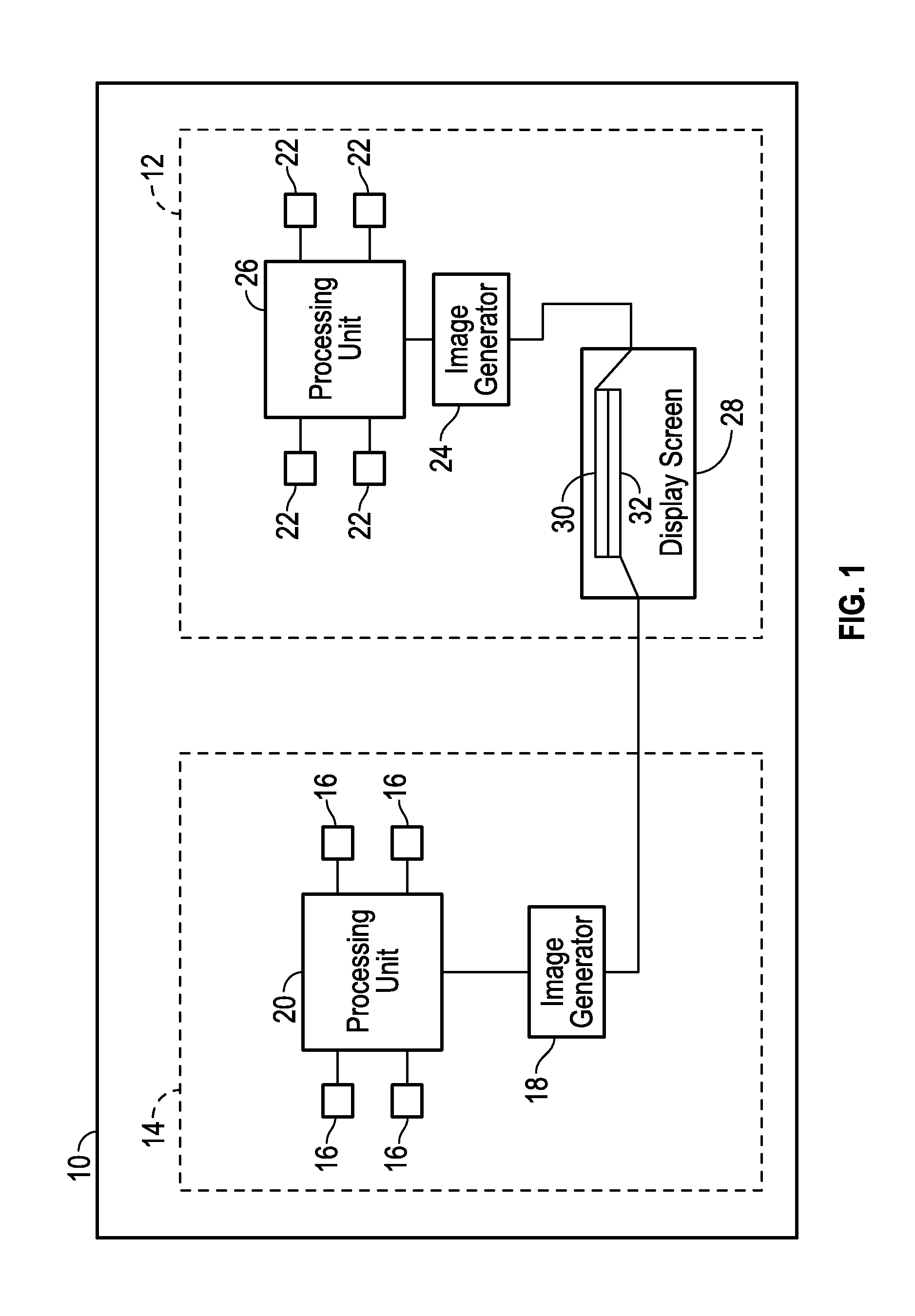
[0018]An improved standby flight display system is disclosed herein. The standby flight display system of the present disclosure is configured for use on an aircraft having a primary flight display system that includes a primary flight display screen on which the primary flight display system displays information relating to a dynamic condition of the aircraft, among other information. The standby flight display system includes one or more subsystems that are configured to detect and / or determine a dynamic condition of the aircraft. Examples of such subsystems include, but are not limited to, Air Data Systems, Attitude Heading Reference Systems, and navigation radios. Such subsystems may inc...


PUM


Abstract

A standby flight display system for use on an aircraft is disclosed herein. The aircraft has a primary flight display system that is configured to display a first image on a primary flight display screen. The standby flight display system includes a subsystem configured to determine a dynamic state of the aircraft. The standby flight display system further includes an image generator. The standby flight display system still further includes a processing unit. The subsystem, the image generator, and the processing unit are each independent of the primary flight display system. The processing unit is communicatively coupled with the subsystem and with the image generator and is configured to receive information from the subsystem relating to the dynamic state of the aircraft and to control the image generator to generate a second image overlaying the first image on the primary flight display screen.

Description

TECHNICAL FIELD[0001]The present invention generally relates to aircraft and more particularly relates to a standby flight display system for backing up a primary flight display system on an aircraft.BACKGROUND[0002]Modern passenger aircraft commonly include a primary flight display system that includes a primary flight display screen that is positioned in a flight deck at a location where it can present information to a member of the flight crew (e.g., pilot, co-pilot). Among other items, a primary flight display system will display information to the pilot relating to the dynamic state of the aircraft while the aircraft is in flight. Such information includes at least the aircraft's altitude, attitude, heading, and airspeed.[0003]Because the aircraft's altitude, attitude, heading, and airspeed are considered critical information, current regulations promulgated by the Federal Aviation Administration and by some foreign counterparts require that there be a redundant display system ...

Claims


Application Information

Patent Timeline
Patent Type & Authority Applications(United States)
IPC IPC(8): B64D43/00
CPCB64D43/00
Inventor MICHAELS, CHARLES
Owner GULFSTREAM AEROSPACE CORP
Why Eureka
Try Eureka