

Motion sensor and analysis
- Summary
- Abstract
- Description
- Claims
- Application Information
AI Technical Summary
Benefits of technology
Problems solved by technology
Method used
Image

Examples
Embodiment Construction
[0078]It should be appreciated that all combinations of the concepts discussed in greater detail below (provided such concepts are not mutually inconsistent) are contemplated as being part of the inventive subject matter disclosed herein. It also should be appreciated that terminology explicitly employed herein that also may appear in any disclosure incorporated by reference should be accorded a meaning most consistent with the particular concepts disclosed herein.
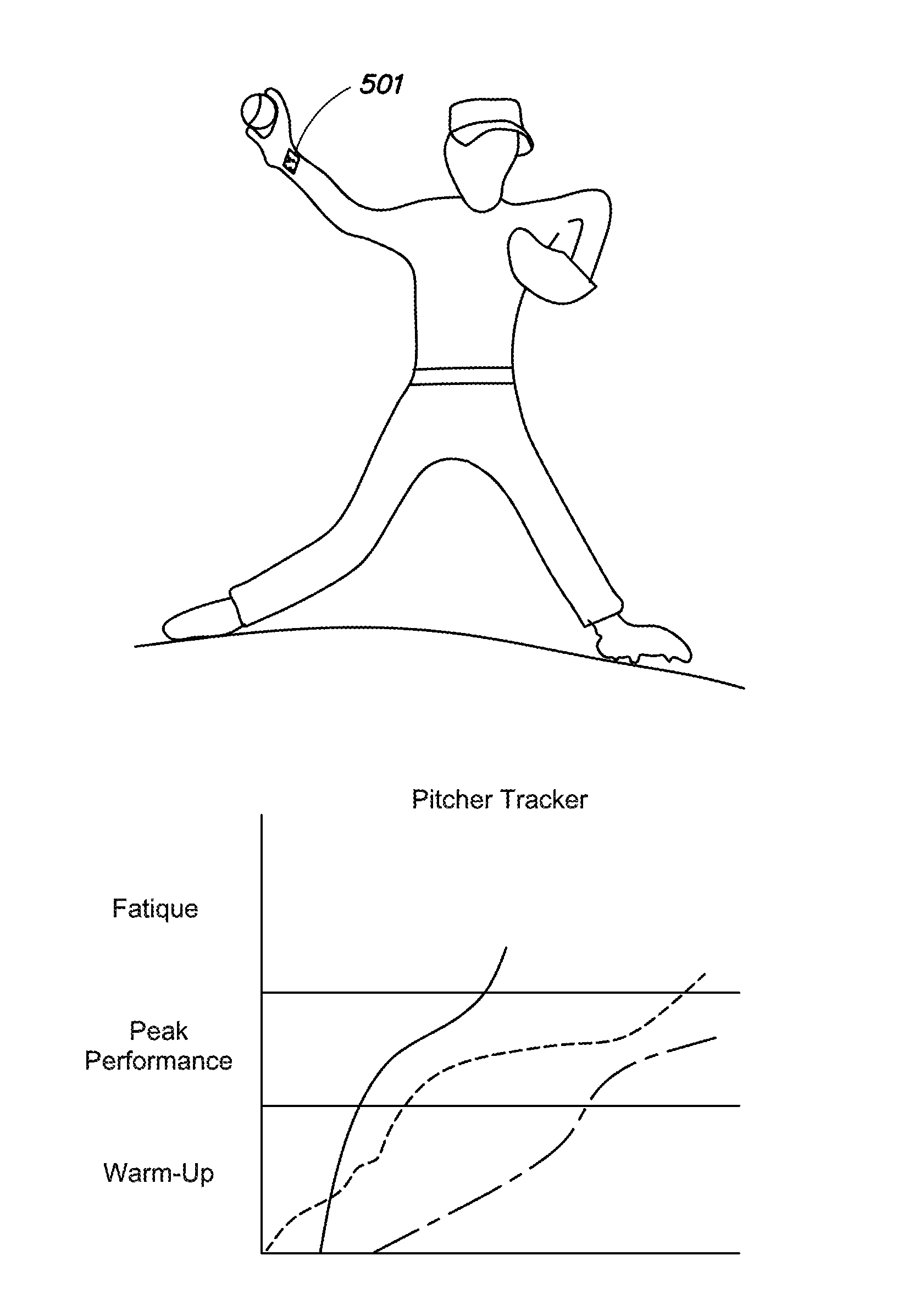
[0079]Following below are more detailed descriptions of various concepts related to, and embodiments of, inventive methods, apparatus and systems for quantifying the performance of an individual using measurement data obtained using a conformal sensor device. According to a non-limiting example, the performance of the individual may be quantified using a parameter referred to as a “throw count,” which serves as a measure of a performance of the individual in a throwing motion and / or a hitting (including licking) an object....
PUM
 Abstract
Description
Claims
Application Information