Rack bush
- Summary
- Abstract
- Description
- Claims
- Application Information
AI Technical Summary
Benefits of technology
Problems solved by technology
Method used
Image
Examples
first modified embodiment
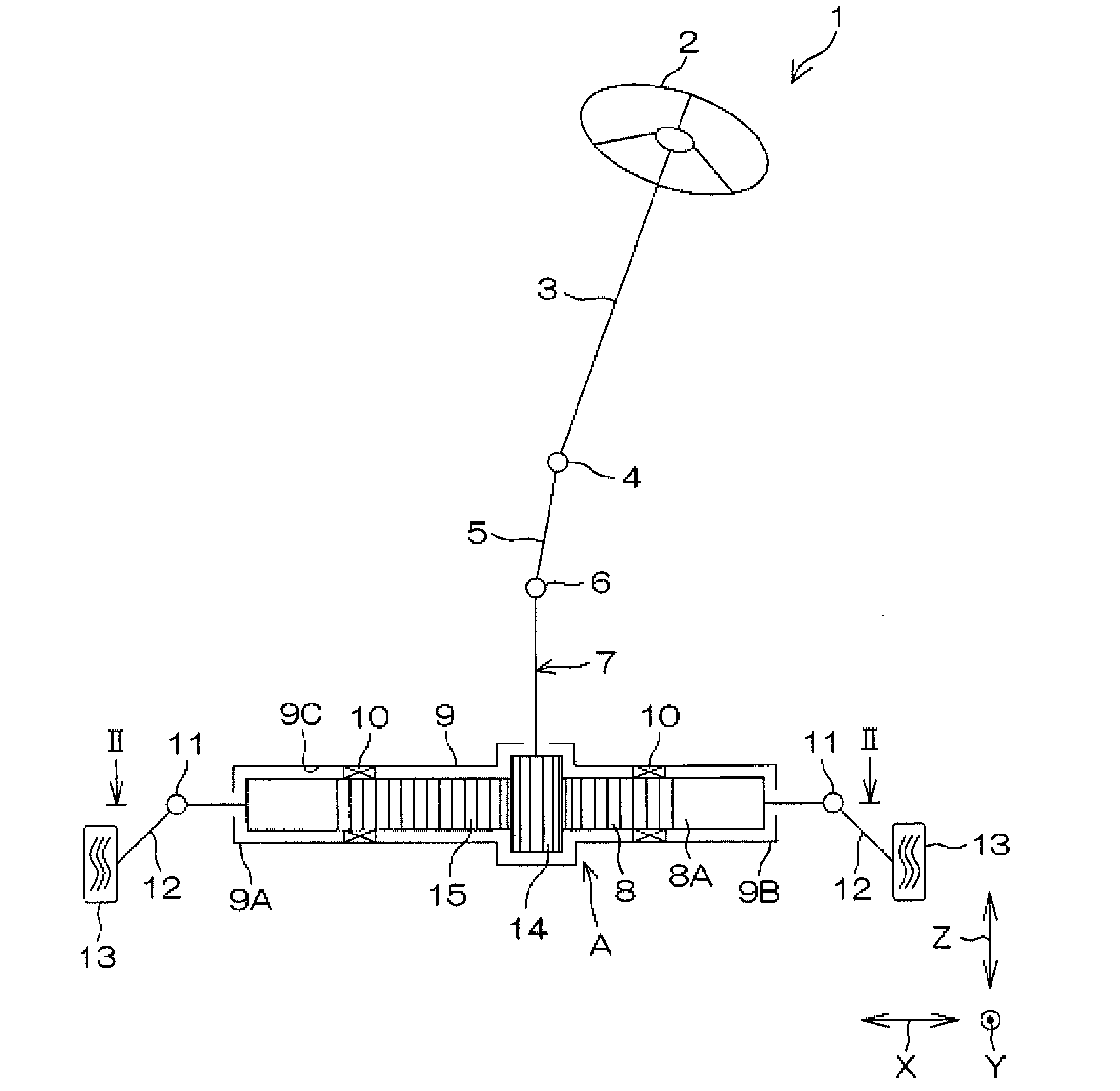
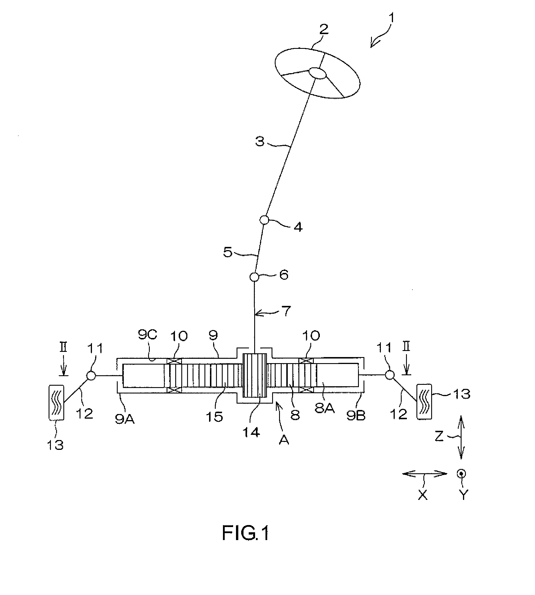
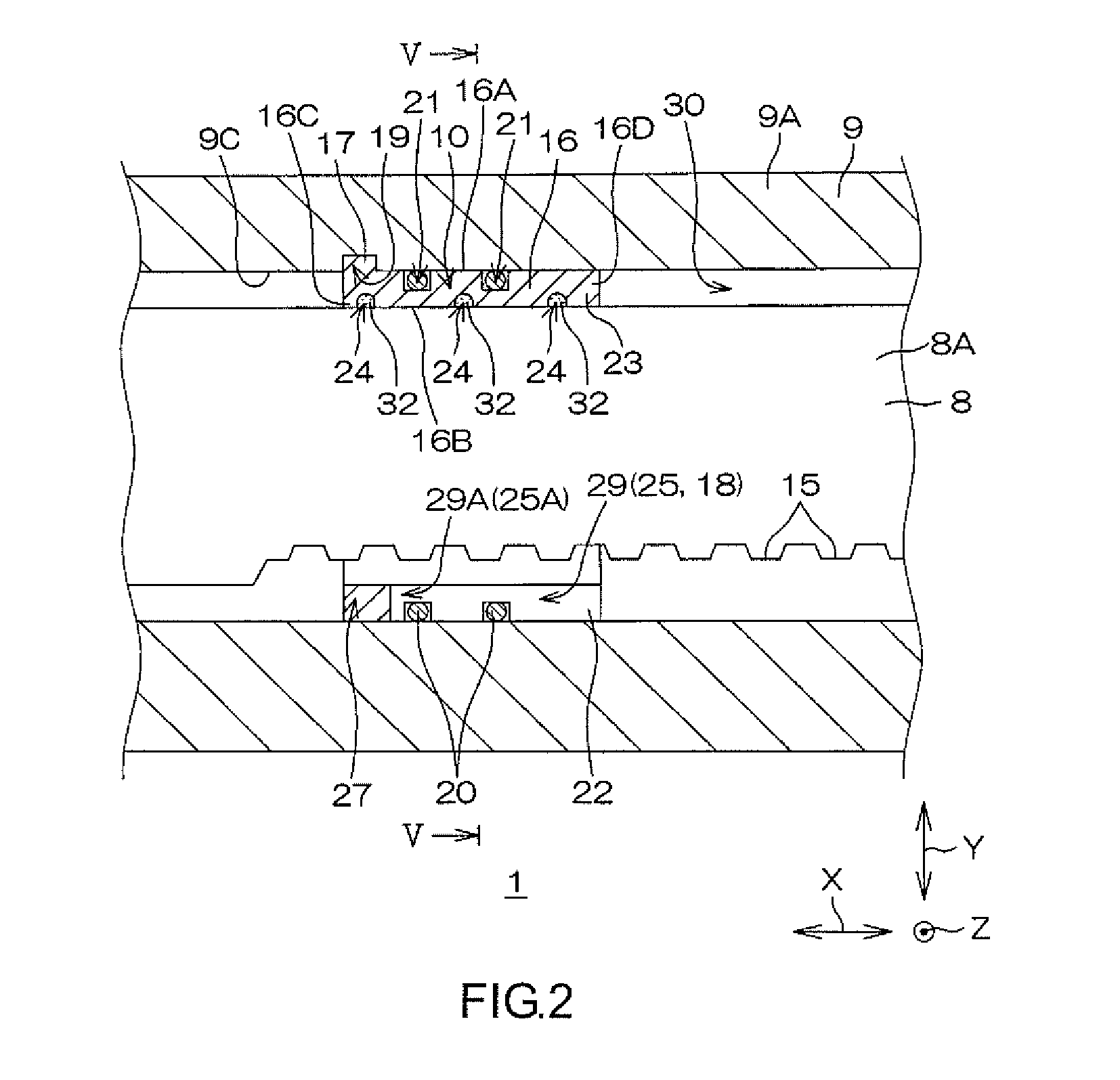
[0046]Next, a first modified embodiment of the present invention will be described. FIG. 6 is a view in which the present invention is applied to FIG. 3. A posture in FIG. 6 coincides with the posture in FIG. 3. The same members as the above-described members will be denoted by the same reference symbols, and the description thereof will be omitted. Hereinafter, the description will be made with reference to FIG. 6 in addition to FIG. 1 to FIG. 5.
[0047]Axial grooves 25 in the first modified embodiment are provided at four portions of a bush main body 16 in a circumferential direction C, and hence the grooves are four axial grooves in total. In the first modified embodiment as well as in the embodiment, one axial groove 25 is provided at each of positions that face each other in a radial direction R so as to be parallel to rack teeth 15. That is, the two axial grooves 25 are respectively provided at boundaries 26 (two circumferential portions) between a rack teeth-side portion 22 and...
second modified embodiment
[0049]The axial grooves 25 in the first modified embodiment are the four axial grooves in total. Thus, the two axial grooves 25 provided at the boundaries 26 at the two circumferential portions extend from the sides opposite to each other to the intermediate positions in the rack teeth-side portion 22. Next, a second modified embodiment and a third modified embodiment of the present invention will be described. FIG. 7 is a view in which the present invention is applied to FIG. 4. FIG. 8 is a view in which the third modified embodiment of the present invention is applied to FIG. 4. Postures in FIG. 7 and FIG. 8 coincide with the posture in FIG. 4. The same members as the above-described members will be denoted by the same reference symbols, and the description thereof will be omitted.
[0050]Hereinafter, the description will be made with reference to FIG. 7 and FIG. 8 in addition to FIG. 1 to FIG. 6. Referring to FIG. 7, in a bush main body 16 in the second modified embodiment, three a...
third modified embodiment
[0053]Furthermore, in the third modified embodiment, only one through hole 31 is formed as a rigidity reducing portion 18 in the rack teeth-side portion 22. In this case, the bush main body 16 has a substantially annular shape (a C-shape) in which one circumferential portion is cut out. Thus, it is possible to easily provide the rigidity reducing portion 18 in the rack teeth-side portion 22, only by providing the one axial groove 25. This invention is not limited to the above-described embodiments, and various modifications may be made in a scope described in claims.
[0054]For example, the number of the axial grooves 25 provided in the rack teeth-side portion 22 may be larger than five, or smaller than four. In short, the number of the axial grooves 25 is not particularly limited, as long as the axial grooves 25 function, as a whole, as the rigidity reducing portion 18 that makes the rigidity of the rack teeth-side portion 22 lower than the rigidity of the back face-side portion 23. ...
PUM
 Abstract
Description
Claims
Application Information
 - R&D
- Intellectual Property
- Life Sciences
- Materials
- Tech Scout
- Unparalleled Data Quality
- Higher Quality Content
- 60% Fewer Hallucinations
Browse by: Latest US Patents, China's latest patents, Technical Efficacy Thesaurus, Application Domain, Technology Topic, Popular Technical Reports.
© 2025 PatSnap. All rights reserved.Legal|Privacy policy|Modern Slavery Act Transparency Statement|Sitemap|About US| Contact US: help@patsnap.com


