LED lighting apparatus having improved flicker performance

a technology of led lighting and flicker performance, which is applied in the direction of lighting apparatus, electrical equipment, light sources, etc., can solve the problems of increasing lighting time, increasing lighting output, and limited load current using current limiting devices, and achieve the effect of improving flicker performan

Active Publication Date: 2015-01-22
LEE DON WON
View PDF10 Cites 2 Cited by
  • Summary
  • Abstract
  • Description
  • Claims
  • Application Information

AI Technical Summary

Benefits of technology

[0024]Accordingly, the present invention has been made keeping in mind the above problems occurring in the prior art, and an object of the present invention is to provide an LED lighting apparatus having improved flicker performance in which the difference between the maximum instantaneous light output and the minimum instantaneous light output from the LED lighting apparatus is decreased.

Problems solved by technology

Consequently, the light output is not uniform and fluctuations with the time, which is problematic.
This consequently increases the lighting time.
3) In addition, the load current was limited using a current limiting device CS2.
Therefore, the section where the minimum instantaneous light output is 0 is not removed, which is problematic.

Method used


Image

  • LED lighting apparatus having improved flicker performance
  • LED lighting apparatus having improved flicker performance
  • LED lighting apparatus having improved flicker performance

Examples


first embodiment

3-Phase AC Power

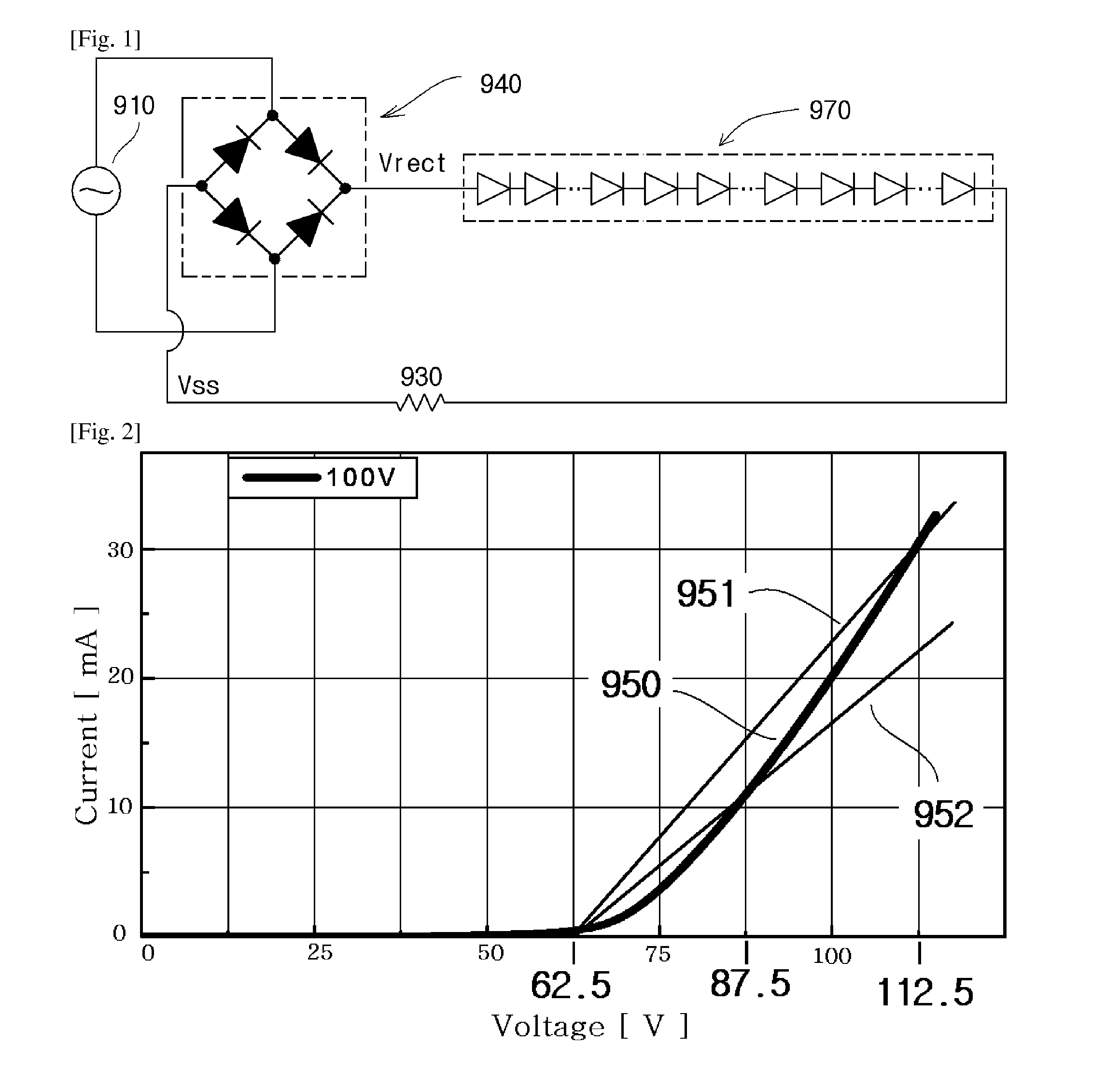
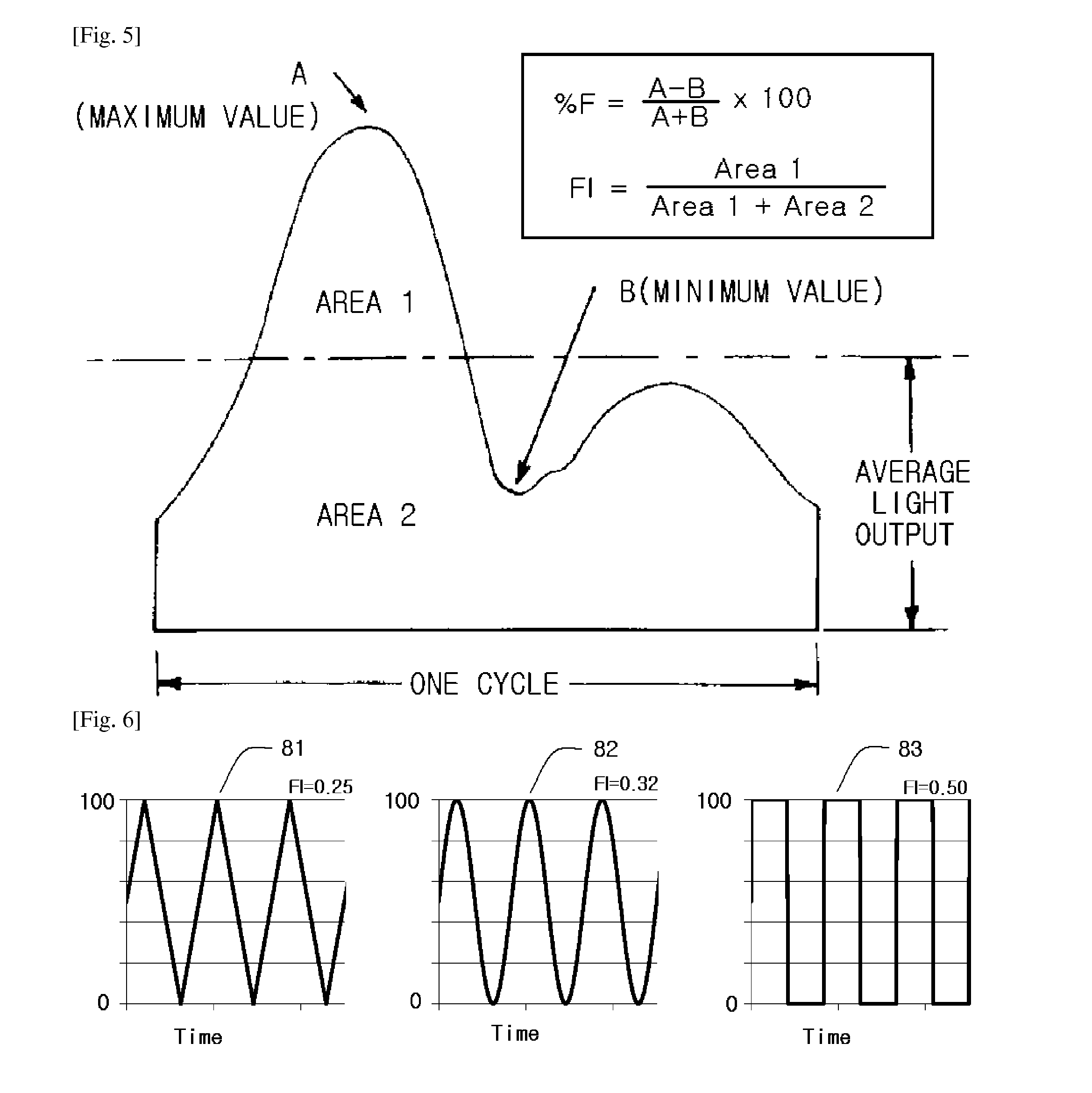
[0081]The first embodiment of the present invention is a specific embodiment in which % F and FI are calculated when the LED lighting apparatus (referring to the entire circuit shown in FIG. 1 or FIG. 4) is provided on the respective phases of a three-phase power supply (hereinafter, the LED lighting apparatus disposed on the respective phases of the three-phase power supply will be referred to as the “LED lighting block”).

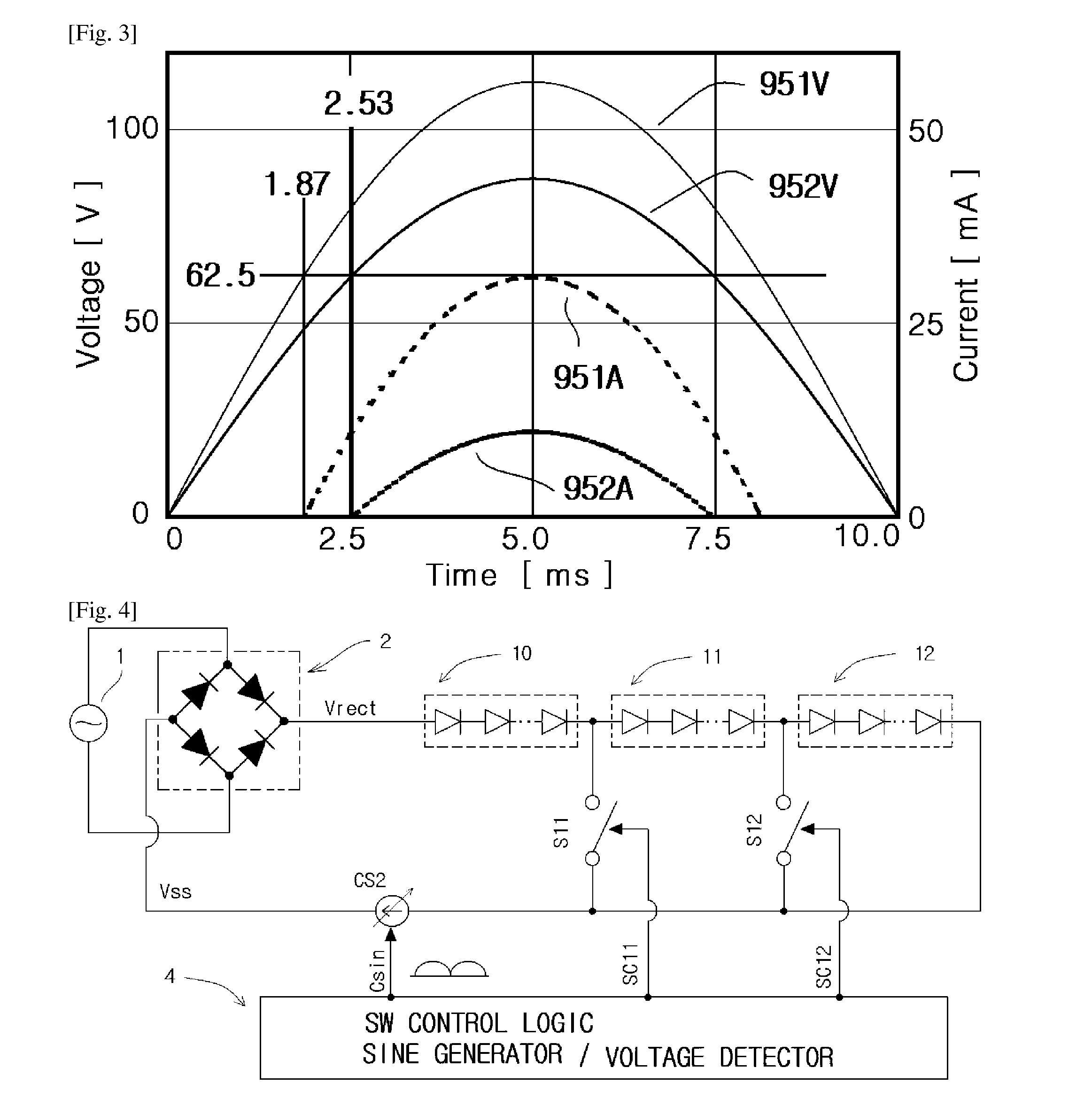
[0082]The circuit configuration employed in the first embodiment includes an AC power supply which supplies a first-phase AC voltage; a first LED lighting block which is driven by the first-phase AC voltage; an AC power supply which supplies a second-phase AC voltage; a second LED lighting block which is driven by the second-phase AC voltage; an AC power supply which supplies a third-phase AC voltage; and a third LED lighting block which is driven by the third-phase AC voltage.

[0083]Describing the first LED lighting block in detail, the first LED l...

second embodiment

Two Phase

[0113]The second embodiment of the present invention is a specific embodiment in which % F and FI are calculated when the LED lighting apparatus (referring to the entire circuit shown in FIG. 1 or FIG. 4) is provided on two phases of a three-phase power supply (hereinafter, the LED lighting apparatus disposed on the two phases of the three-phase power supply will be referred to as the “LED lighting block”).

[0114]The circuit configuration employed in the second embodiment includes an AC power supply which supplies a first-phase AC voltage; a first LED lighting block which is driven by the first-phase AC voltage; an AC power supply which supplies a second-phase AC voltage; and a second LED lighting block which is driven by the second-phase AC voltage.

[0115]Describing the first LED lighting block in detail, the first LED lighting block includes a first rectifier circuit which rectifies the first-phase AC voltage; a first LED block composed of one or more LEDs which are driven ...


PUM


Abstract

Provided is a lighting apparatus using LEDs (light-emitting diodes having improved flicker performance. In general, in a direct-drive LED lighting apparatuses of the related art which use no switching-mode power supply (SMPS), percent flicker (hereinafter referred to as “% F”) is 100%. In contrast, the % F of the LED lighting apparatus having improved flicker performance according to the present invention is 40% or less that is equivalent to the % F of fluorescent lamps using a magnetic ballast.

Description

BACKGROUND[0001]The present invention relates, in general, to a lighting apparatus using light-emitting diodes (LEDs) and, more particularly, to an LED lighting apparatus having improved flicker performance which is driven directly by a rectified voltage without using a typical switching mode power supply (SMPS).[0002]Light-emitting diodes (LEDs) are electrophotonic conversion semiconductor devices that emit light when current flows therethrough, and are widely used for indicators, backlights, etc. The electrophotonic conversion efficiency of LEDs is higher than that of incandescent lamps and that of fluorescent lamps in response to the development of technologies, and their range is expanding to general lighting systems.[0003]Among methods of driving an LED, a plurality of methods of driving an LED lamp using a rectified voltage without a typical switching mode power supply (SMPS) (hereinafter referred to as “LED direct drive methods”), including Patent No. 10-1110380 of the invent...

Claims


Application Information

Patent Timeline
Patent Type & Authority Applications(United States)
IPC IPC(8): H05B33/08H05B44/00
CPCH05B33/0809H05B33/0827H05B33/083H05B45/48H05B45/46
Inventor LEE, DON, WON
Owner LEE DON WON
Why Eureka
Try Eureka