
Anti-counterfeit and Anti-theft buttons

a technology applied in the field of anti-counterfeit and anti-theft buttons, can solve the problems of complicated process, increased cost, uncontrollable management, etc., and achieve the effect of enhancing the effect of receiving signals

Inactive Publication Date: 2015-01-22
HUANG SHENG CHANG +1
View PDF2 Cites 20 Cited by
  • Summary
  • Abstract
  • Description
  • Claims
  • Application Information

AI Technical Summary

Benefits of technology

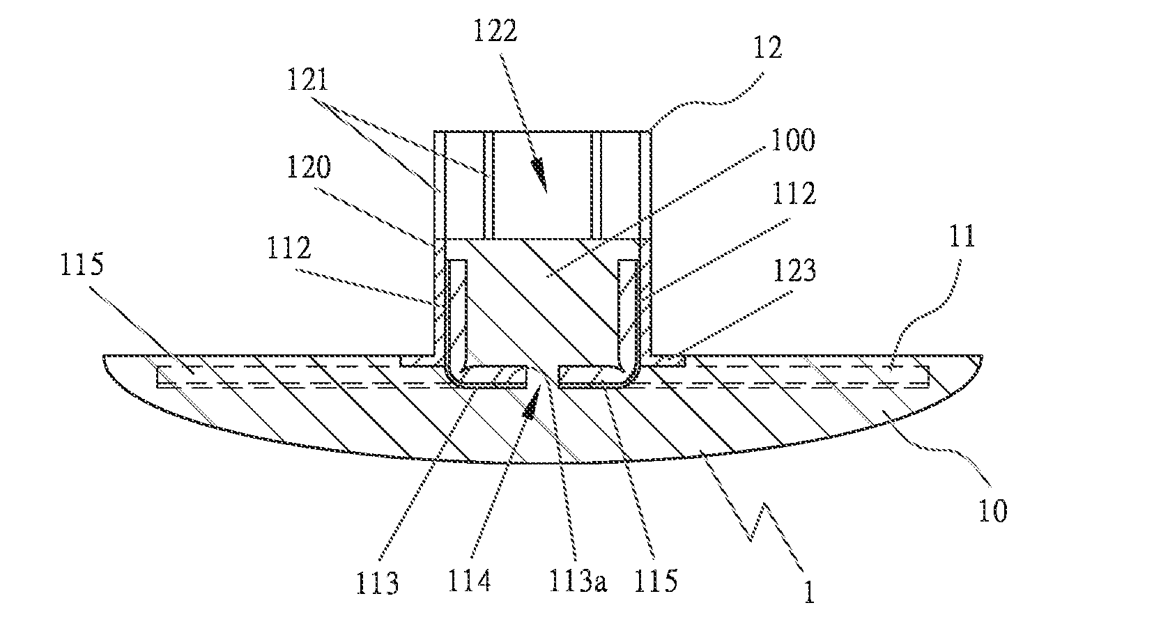
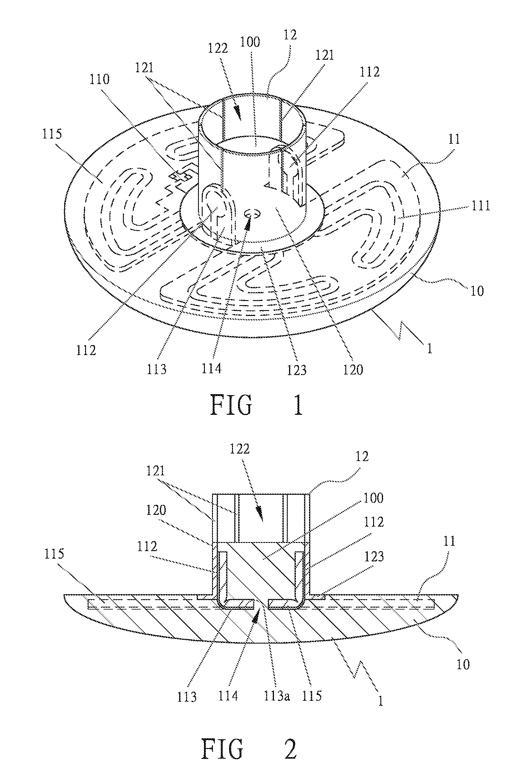
The patent describes an anti-counterfeit and anti-theft button that can be used to prevent items from being taken out of markets without permission. The button contains a RFID chip that can be connected to an antenna, which enhances the reception of signals. The buttons can be used in pairs, with their antennas locked together to create a short or closed circuit. When the buttons are separated, the system can sound a warning to alert against theft or counterfeiting.

Problems solved by technology

With each article engaged with an anti-theft button before selling out and separated from it after selling out, it takes a complicated process stepping up cost and making management uneasy to control.
However, as the RFID anti-theft device has to combine the annular RFID tag with the displaying member to achieve an anti-theft purpose, it also takes a complicated process with cost soared, only available for high-priced articles, not for tiny cheap articles or flexible articles, such as clothes.

Method used


Image

  • Anti-counterfeit and Anti-theft buttons
  • Anti-counterfeit and Anti-theft buttons
  • Anti-counterfeit and Anti-theft buttons

Examples


first embodiment

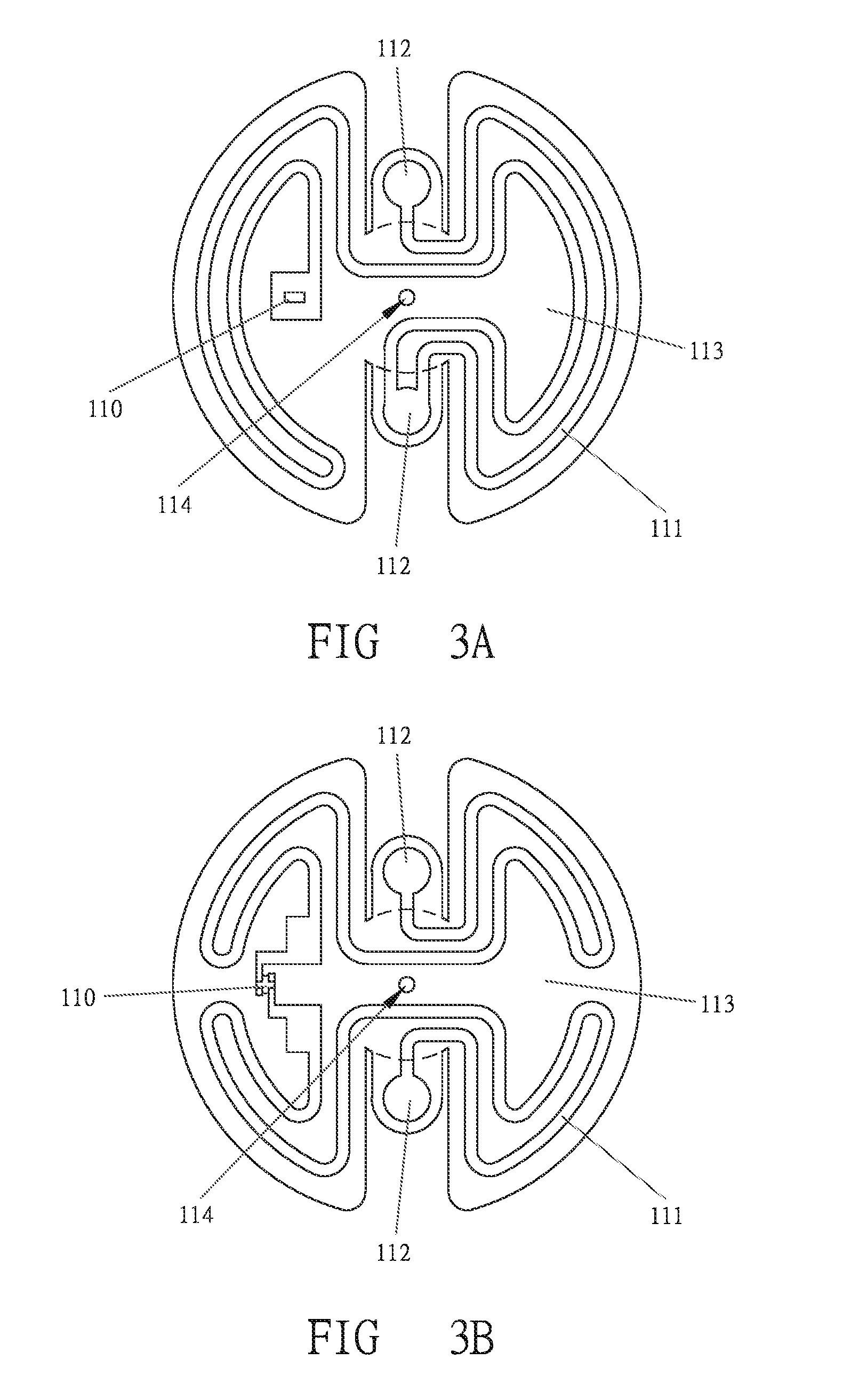
[0031]FIG. 3A shows installing the RFID chip 110 and the antenna 111 of the RFID system 11 in a circuit board 113. In this embodiment, the RFID system 11 contains a single RFID chip 110 that is of HF or UHF, and the antenna 111 is of a single circuit. Two extended antennas 112 are located at proper positions of the antenna 111, partly separated from the circuit board 113 for being appropriately curved toward one side. The circuit board 113 is properly bored with a hole 114 provided as a flowing hole to cast raw plastics.

second embodiment

[0032]FIG. 3B shows installing the RFID chip 110 and the antenna 111 of the RFID system 11 in a circuit board 113. In this embodiment, the RFID system 11 contains a single RFID chip 110 that is of HF or UHF, and the antenna 111 is of double circuits. Two extended antennas 112 are located at proper positions of the antenna 111, partly separated from the circuit board 113 for being appropriately curved toward one side. The circuit board 113 is properly bored with a hole 114 provided as a flowing hole to cast raw plastics.

third embodiment

[0033]FIG. 3C shows installing the RFID chip 110 and the antenna 111 of the RFID system 11 in a circuit board 113. In this embodiment, the RFID system 11 contains a single RFID chip 110 that is of HF or UHF, and the antenna 111 is of triple circuits or more. Three extended antennas 112 are located at proper positions of the antenna 111, partly separated from the circuit board 113 for being appropriately curved toward one side. The circuit board 113 is properly bored with a hole 114 provided as a flowing hole for casting raw plastics.


PUM


Abstract

Anti-counterfeit and anti-theft buttons include at least a body embedded with a RFID system containing one or plural RFID chips. Each RFID chip may be of a single or double or multiple frequencies. If the single frequency is used, it may be a high frequency (HF) or an ultrahigh frequency (UHF). If the double frequencies are used, they may be any composition of HF and UHF. If the multiple frequencies are used, they may be a single HF and plural UHF, or plural HF and single UHF. The RFID chip is jointed with an antenna that may be of a single or multiple circuits and should have an extended antenna. All antennas can enhance effects of receiving signals. When two of these buttons fitted together are illegally separated, a system host may operate to give out warning signals or sound, achieving counterfeit and theft prevention.

Description

BACKGROUND OF THE INVENTION[0001]1. Field of the Invention[0002]This invention relates to anti-counterfeit and anti-theft buttons, particularly to ones having a body embedded with a RFID system containing one or plural RFID chips, with each RFID chip being of a single or double or multiple frequencies and jointed with an antenna that may be of a single or multiple circuits. Combined with an extended antenna, an auxiliary antenna that the button body has can enhance effects of receiving signals. If two of these buttons fitted together are illegally separated, a system host may operate to give out warning signals or sound, achieving counterfeit and theft prevention.[0003]2. Description of the Prior Art[0004]Commonly, commodities sold in open markets, department stores or supermarkets are engaged with conventional anti-theft buttons to prevent them from being stolen. As an article is sold out, the anti-theft button is to be detached from it by a particular tool at a checkout counter so...

Claims


Application Information

Patent Timeline
Patent Type & Authority Applications(United States)
IPC IPC(8): G06K19/077
CPCG06K19/0775G06K19/07724G06K19/07798G06K19/07758G08B13/2402G06K19/07786G08B13/2417G08B13/2431G08B13/2434G08B13/2448G08B29/046
Inventor HUANG, SHENG-CHANG
Owner HUANG SHENG CHANG
Learn More