Photographic apparatus and method

a technology for photographing and apparatus, applied in the field of photographs, can solve the problems of moving subjects offering additional complications, requiring and time constraints, and being required to generate images under potentially very difficult lighting conditions, and achieve the effect of changing the lighting direction, projection and quality of light very quickly and effortlessly, and unlimited flexibility

Active Publication Date: 2015-01-22
SHAPIR YISHAI
View PDF2 Cites 0 Cited by
  • Summary
  • Abstract
  • Description
  • Claims
  • Application Information

AI Technical Summary

Benefits of technology

[0011]In accordance with one or more embodiments of the present invention, the photographer artist is able to control, redirect and bounce light from a portable flash unit, thus changing the lighting direction, projection and quality of light very quickly and effortlessly while providing unlimited flexibility with one or more various attachments to the flash.
[0012]Therefore, in accordance with embodiments of the present invention, an improved flash adapter is provided that allows for a complete 360 degrees in rotation for the movement of any attached diffuser, reflector, bounce card or the like relative to the portable flash, in addition to any flash head rotation, resulting in greater flexibility to control and redirect light quickly. As will be described in greater detail below, various embodiments of the present invention allow the user to control the light by allowing for direction of light in 360 degrees around a portable flash head with only slight wrist action, similar to that employed for rotating a lens for zooming or focusing, with photographers already being accustomed to such adjustments.
[0013]In addition to flexibility provided for reflector and bounce cards, other accessory attachments may also benefit from various embodiments of the present invention, such as attachments that may be employed in accordance with the shooting of both video and still pictures substantially simultaneously. Therefore, in accordance with various embodiments of the present invention, one may attach a video light, boom microphone or the like, and control their respective angles in accordance with various embodiments of the apparatus and method of the present invention.
[0014]Furthermore, a photojournalist or event photographer that may be under time constraints when dealing with potentially difficult lighting circumstances will have the extra flexibility to properly, quickly and easily light their subjects, without wasting critical moments or loosing potential images.

Problems solved by technology

Currently available lighting techniques are designed to address a variety of problems yet still exhibit a number of deficiencies.
A photojournalist or event photographer may be required to generate images under potentially very difficult lighting conditions, requirements and time constraints.
Often, moving subjects may offer additional complications, such as when a celebrity or other person shakes a hand and moves along, potentially continuously or intermittently.
Furthermore, existing on-camera flash units offer a very small and portable light source, but potentially generate extremely harsh lighting, thereby resulting in potentially unflattering pictures.
However, the problem of such a small light source offering a harsh, flat appearance still remains.
While the equipment described above provides good lighting effects in a fixed studio setting, it can be inconvenient if not impossible to use such stationary lighting accessories outside of the photography studio.
However, known portable diffusers for use with on-camera flashes are less than ideal in terms of the quality of lighting produced.
These diffusers tend to create hotspots and may also leave noticeable, undesirable shadows.
Furthermore, such diffusers do not allow for light to be directed in one or another desired direction from such a portable light source.
Existing flashcard attachments, such as reflectors or bounce cards which are stationary on the flash, may hinder the photographer from creating different quality directional lighting.
Thus, the photographer is generally unable to modify a lighting presentation without a potentially lengthy and time consuming sequence of events.

Method used


Image

  • Photographic apparatus and method
  • Photographic apparatus and method
  • Photographic apparatus and method

Examples


Embodiment Construction

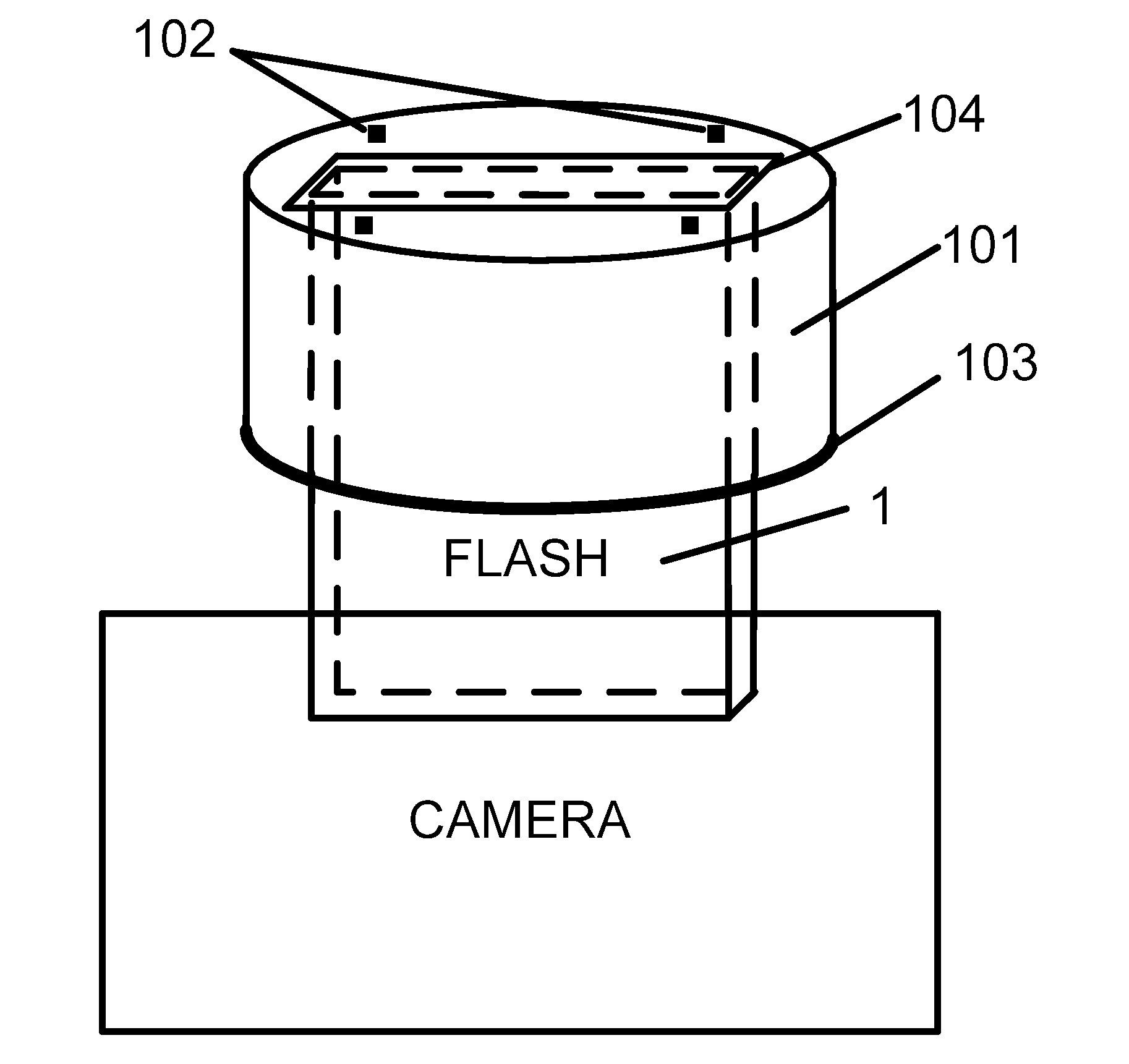
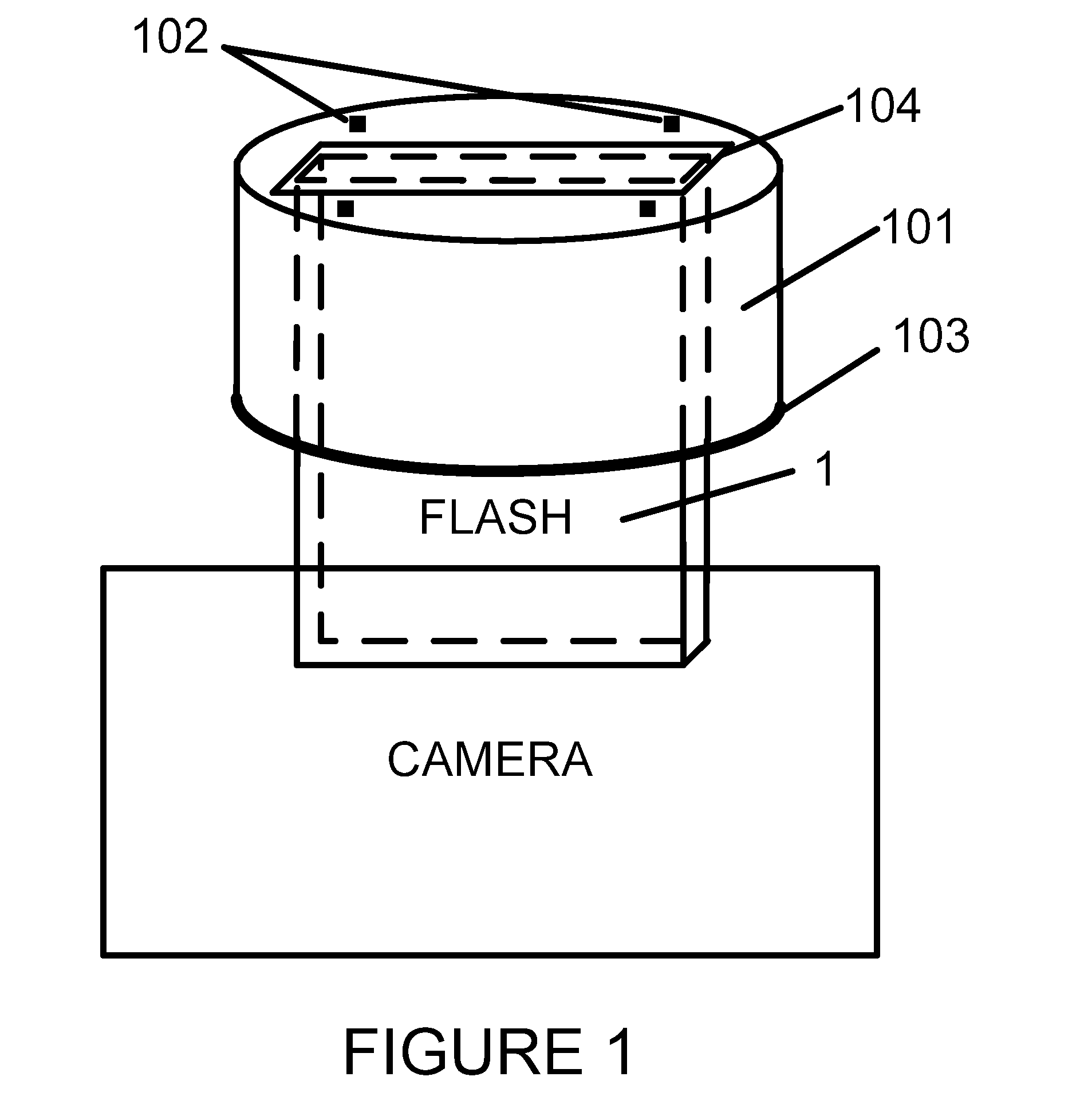
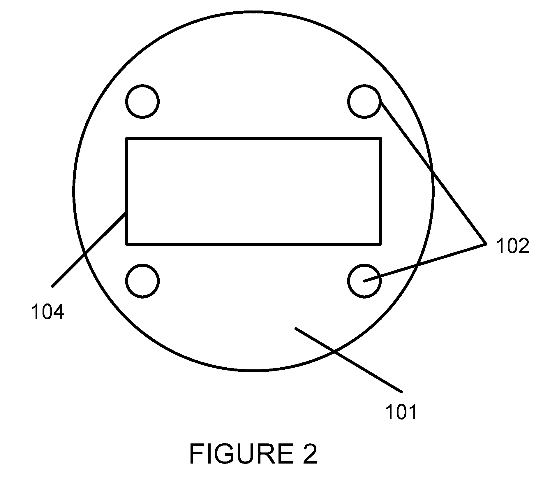
[0031]The invention will now be described making reference to the following drawings in which like reference numbers denote like structure or steps. The subject improved photographic apparatus is preferably comprised of several cooperating elements as detailed below and shown in the accompanying figures.

[0032]Referring first to FIGS. 11 and 12, a first preferred embodiment of an apparatus 100 is shown attached to a compact, conventional flash unit 1 (see FIG. 12). Various embodiments are preferably comprised of several cooperating elements which are adapted to engage and operate in the following manner. A first part of apparatus 100 may comprise a round or oval sleeve 2 defining a generally centrally located inner opening configured to compliment the shape of a particular conventional photographic flash unit 1, as shown in FIG. 12. Thus, in accordance with various embodiments of the invention, sleeve 2 is dimensioned to be coupled with flash unit 1. A fastening strap 5 may alternati...


PUM


Abstract

A photographic flash attachment apparatus. The apparatus includes a sleeve configured to be fixed to a photographic flash, a ring configured to engage with the sleeve, and one or more attachment mechanisms coupled with the ring adapted to receive one or more photographic attachment elements. Upon attachment of one or more photographic attachment elements to the ring via the one or more attachment mechanisms, rotation of the ring provides rotation of the one or more photographic attachment elements relative to the photographic flash.

Description

CROSS REFERENCE TO RELATED APPLICATION[0001]This application is a continuation of U.S. patent application Ser. No. 13 / 158,403 to Shapri, filed Jun. 11, 2011, titled “Photographic Apparatus and Method”, which in turn claims the benefit of U.S. Provisional Patent Application Ser. No. 61 / 354,901 to Shapir, filed Jun. 15, 2010, titled “Photographic Apparatus and Method”, the entire contents of each of these applications being incorporated herein by reference.FIELD OF THE INVENTION[0002]This invention relates generally to aids for taking photographs, and more particularly to a method and apparatus for assisting in directing light from a flash when taking pictures.BACKGROUND OF THE INVENTION[0003]Currently available lighting techniques are designed to address a variety of problems yet still exhibit a number of deficiencies. Prior examples of photographic light diffusers and deflectors may be seen in U.S. Pat. Nos. 5,311,409, 5,839,006, and 7,380,966, each of which is incorporated herein b...

Claims


Application Information

Patent Timeline
Patent Type & Authority Applications(United States)
IPC IPC(8): G03B15/02G03B15/06
CPCG03B15/06G03B15/02G03B15/05G03B17/568G03B2215/0592G03B17/56
Inventor SHAPIR, YISHAI
Owner SHAPIR YISHAI
Why Eureka
Try Eureka