
Loudspeaker impedance matching device for non-permanent applications

a technology for loudspeakers and impedance matching, applied in the direction of basic electric elements, electric transducers, electrical apparatus, etc., can solve the problems of reducing efficiency, reducing acoustic output, and increasing the complexity of the system, and achieve the effect of unlimited design flexibility

Active Publication Date: 2019-11-05
WIERSUM ENTERPRISES INC
View PDF7 Cites 0 Cited by
  • Summary
  • Abstract
  • Description
  • Claims
  • Application Information

AI Technical Summary

Benefits of technology

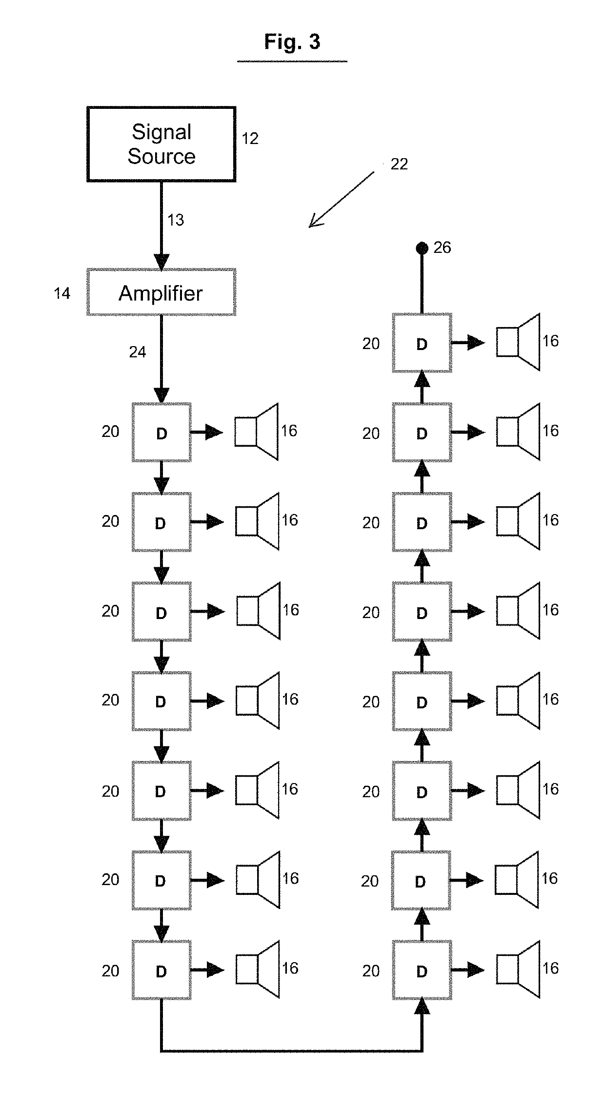
The present invention provides an apparatus that can connect multiple loudspeakers economically and efficiently with reduced energy loss. It is portable and can be easily attached to different brands or manufacturers of amplifiers and loudspeakers. The device is flexible and can be designed in different configurations.

Problems solved by technology

The complexity of the system can be increased, however, as each loudspeaker cabinet or enclosure needs to be supplied with an audio signal, power, and possibly also a data / control signal.
It should be noted that most amplifiers can also operate at impedances greater than 8 ohms, but with reduced efficiency, resulting in a lower acoustical output.
Such a setup is also at a disadvantage due to the nature of this setup operating at a relatively low voltage but with high current.
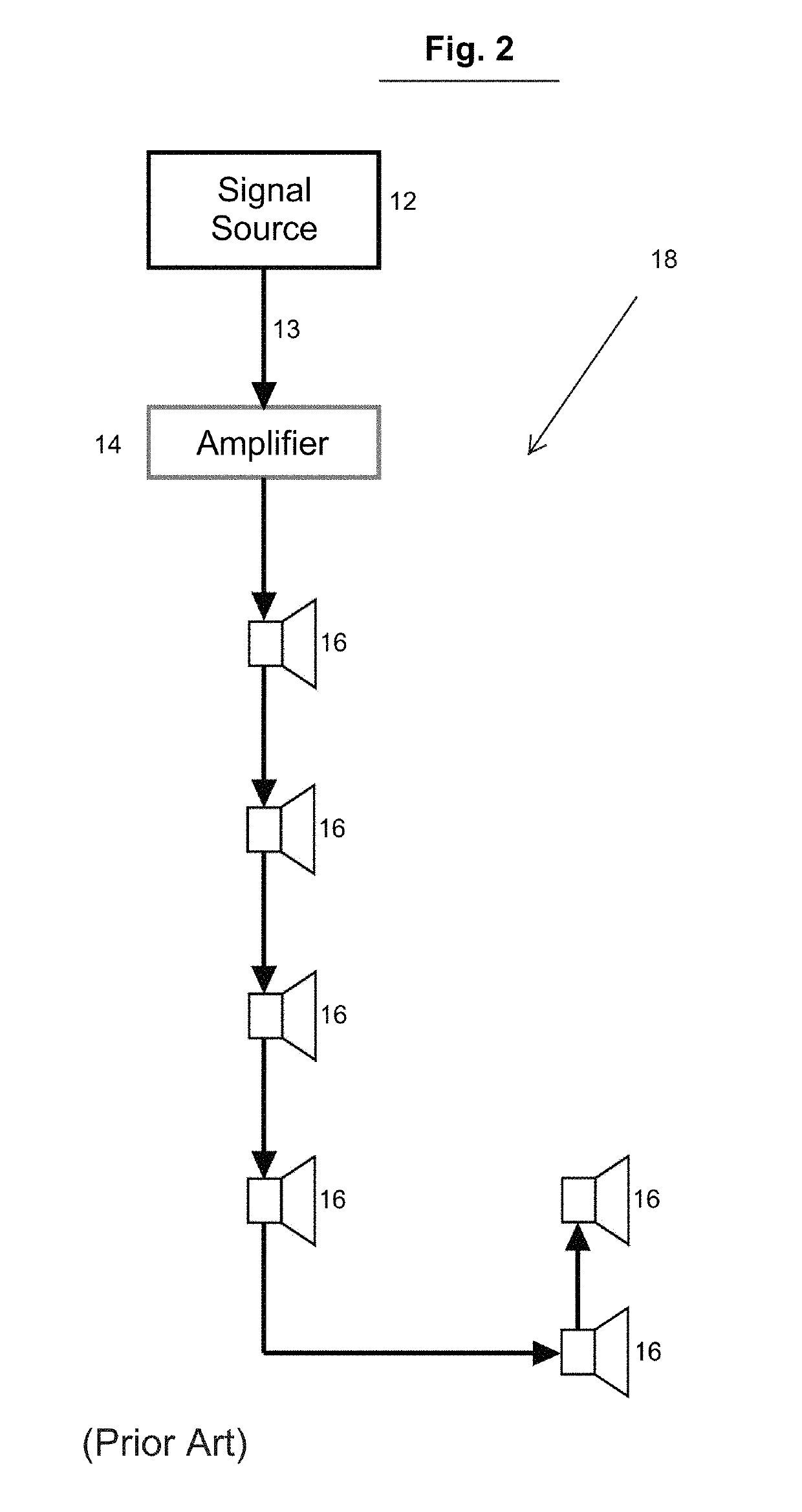
Loudspeakers can also be wired in series, which increases the overall system impedance.
This can lead to issues with the aforementioned amplifier operating inefficiently at impedances greater than 8 ohms.
Such wiring methods are further burdensome by making troubleshooting difficult.
A wiring fault or component failure anywhere in the system will disable the entire system.
Each impedance matching device has its own inefficiencies, commonly referred to as an insertion loss.
The insertion losses are typically mitigated by the line loss and resultant cost of larger cabling and a higher quantity of amplifiers that would be required by a low impedance system.
These loudspeakers are not typically designed for portable or temporary applications, and lack many features desirable for temporary applications.
Readily available portable loudspeakers could be modified so as to include an impedance matching device with a bypass switch, but with the disadvantage of increased and undesirable weight.

Method used


Image

  • Loudspeaker impedance matching device for non-permanent applications
  • Loudspeaker impedance matching device for non-permanent applications
  • Loudspeaker impedance matching device for non-permanent applications

Examples


Embodiment Construction

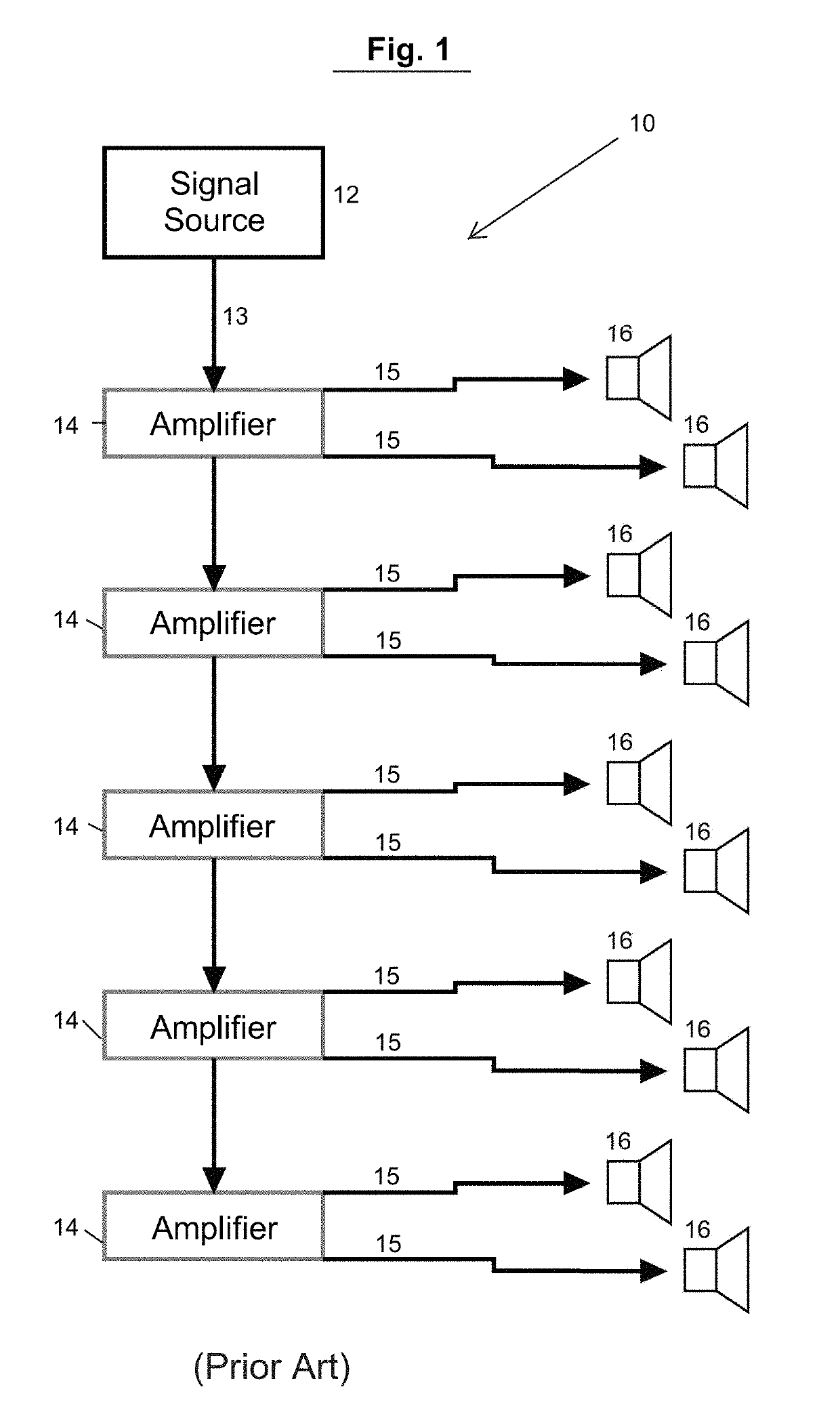
[0035]Referring now to the drawings, FIG. 1 illustrates a block diagram of a first conventional setup 10 for temporarily connecting a plurality of speakers to a signal source. The output 13 of a signal source or audio source 12 is connected to plurality of amplifiers 14 whose inputs are connected in parallel. An output 15 of each amplifier 14 is connected to a loudspeaker or loudspeakers 16. Loudspeaker or loudspeakers 16 can be connected directly to the amplifiers 14, with a few restrictions. The total impedance of all the connected loudspeakers 16 must be within the working limits of each of the amplifiers 14. As more loudspeakers 16 are added, the overall impedance decreases. Eventually, the impedance decreases to a value that is outside of what any amplifier can reasonably be expected to power, and moreover, the value can become so low that cable size and quantity quickly become impractical or cost prohibitive.

[0036]Additional amplifiers can be utilized to distribute the quantit...


PUM

PropertyMeasurementUnit
impedanceaaaaaaaaaa
impedanceaaaaaaaaaa
impedanceaaaaaaaaaa

Abstract

An impedance matching device including a transformer having an input side and an output side, wherein the input side includes a first coil having a first impedance, a second coil having a second impedance, and a third coil having a third impedance. An input power connector is electrically connected to the input side of the transformer, and a pass through output power connector is electrically connected to the input side of the transformer, and the pass through output connector also is electrically connected in parallel to the input power connector. A speaker output connector having four electrical contacts is included, wherein a first pair of the four electrical contacts is connected electrically to the first coil, and a second pair of the four electrical contacts is connected electrically to the second coil.

Description

BACKGROUND OF THE INVENTIONField of the Invention[0001]The present invention relates to impedance matching devices for use with sound reinforcement or playback loudspeakers for non-permanent applications, and more particularly, to improving efficiency of impedance matching within a temporary setup of a plurality of loudspeakers arranged at an outdoor event.Description of Related Art[0002]It is known in the prior art of several common practices for setting up and distributing signals to loudspeakers for various temporary or non-permanent applications. For example, a series of high power, often long-throw loudspeakers are typically provided in a centralized location. Such systems are often colloquially referred to as a “line array” and are typically supplied on either side of a stage for concert live sound reinforcement applications. Such arrays can also be free standing (ground stacked) or suspended independently from freestanding towers. Systems of this design are often employed to ...

Claims


Application Information

Patent Timeline
Patent Type & Authority Patents(United States)
IPC IPC(8): H04R9/02H04R3/12H01F27/28
CPCH04R3/12H01F27/2828H04R9/02H01F19/02H04R3/007H04R2227/005
Inventor WIERSUM, BENJAMIN K.
Owner WIERSUM ENTERPRISES INC
Learn More