Crimping structure of cable connector

a technology of crimping structure and cable connector, which is applied in the direction of electrical equipment, connections, and connections effected by permanent deformation, etc. it can solve the problems of increasing manufacturing costs, requiring a more complicated and laborious manufacturing and assembly process, and requiring more components. , to achieve the effect of ensuring signal transmission quality more positively and reliably, facilitating installation and application, and improving waterproof performan

Inactive Publication Date: 2015-01-22
LU YUEH CHIUNG
View PDF3 Cites 12 Cited by
  • Summary
  • Abstract
  • Description
  • Claims
  • Application Information

AI Technical Summary

Benefits of technology

[0013]1. The invention provides better waterproof performance to assure signal transmission quality more positively and reliably.
[0014]2. The invention provides a more secured and reliable fixing effect of the electric cable.
[0015]3. The invention requires less components of the overall crimping structure of a cable connector, and provides easier installation and application.
[0016]4. The overall crimping structure of a cable connector gives a better water resisting effect with by using less number of components, not just lowering the manufacturing cost, but also improving the product competitiveness.

Problems solved by technology

However, such arrangement requires more components in the overall cable connector, not just incurring a higher manufacturing cost, but requiring a more complicated and laborious manufacturing and assembling process.
However, the crimping effect will not be increased with the level of pressing the outer collar towards the circular body, but it will be displaced with the outer collar to change the crimping position, and thus having no significant improvement on the fixing effect of the electric cable and the water resisting effect of the cable connector.
Therefore, the electric cable inside the connector still may be shaken by strong wind and / or external force, and the signal transmission quality may be affected adversely.

Method used


Image

  • Crimping structure of cable connector
  • Crimping structure of cable connector
  • Crimping structure of cable connector

Examples


Embodiment Construction

[0024]The present invention will become clearer in light of the following detailed description of an illustrative embodiment of this invention described in connection with the drawings. It is intended that the embodiments and drawings disclosed herein are to be considered illustrative rather than restrictive.

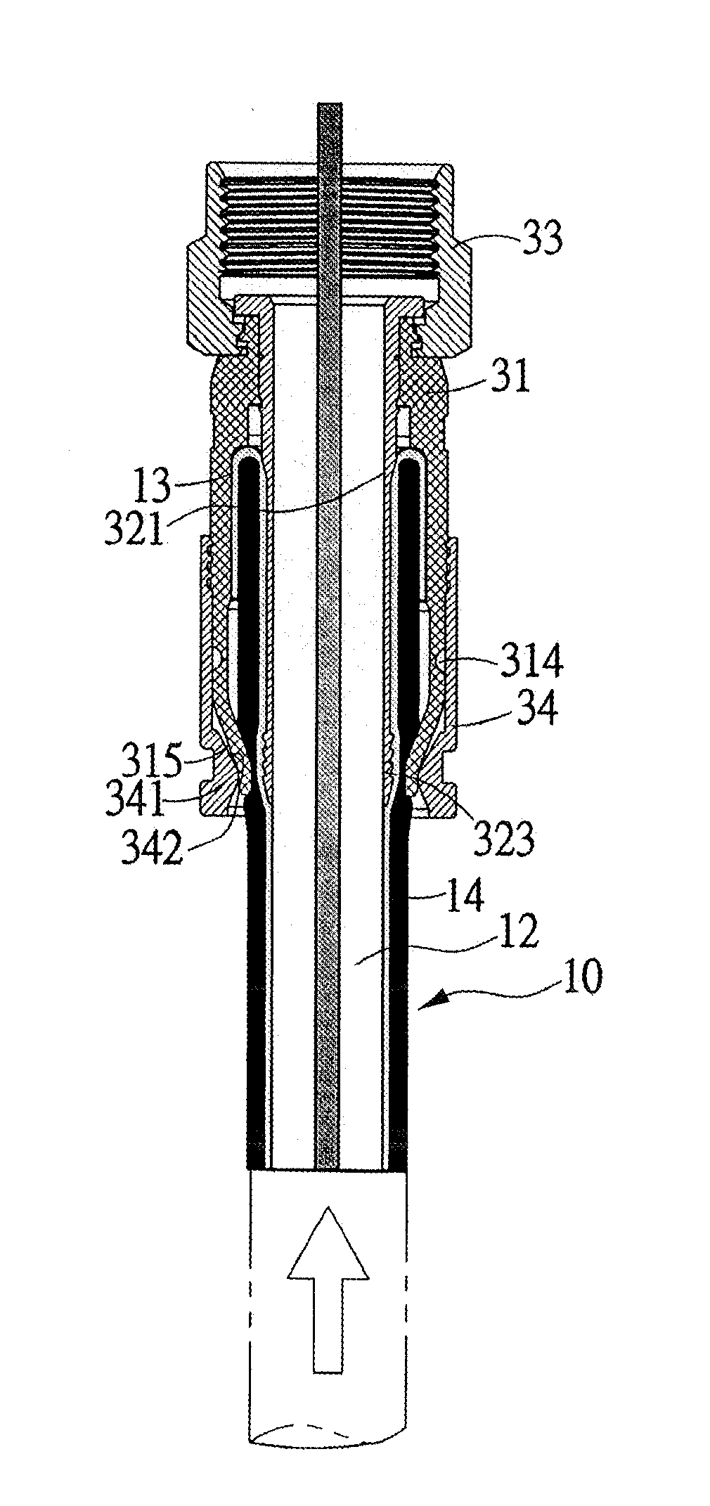
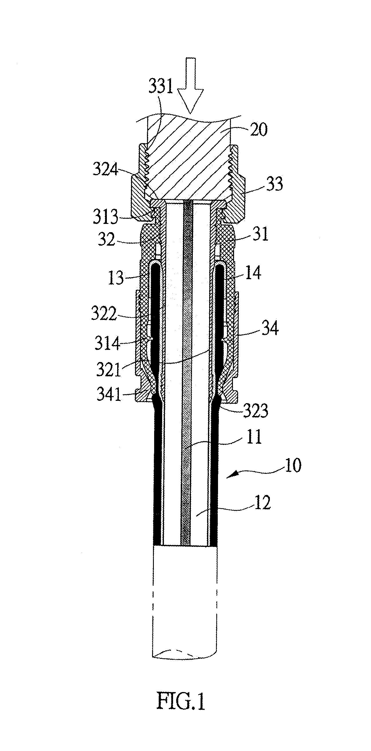
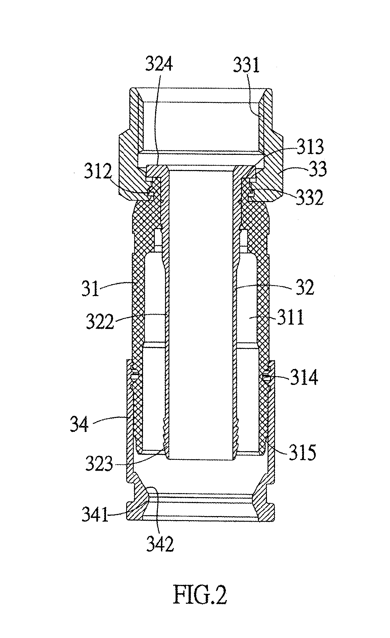
[0025]With reference to FIG. 1 for a cross-sectional view of a using status of a crimping structure of a cable connector in accordance with the present invention, the crimping structure is installed at a rear end of an electric cable 10 for connecting the electric cable 10 to an engaging element 20 quickly. With reference to FIG. 2, the crimping structure of a cable connector of the present invention comprises a plastic ring 31, an internal hollow pillar 32, a circular nut 33, and an outer collar 34.

[0026]The plastic ring 31 includes a cable passing section 311 disposed therein for accommodating the hollow pillar 32 and the electric cable 10, an embedding slot 312 formed around ...


PUM


Abstract

A crimping structure includes a plastic ring, an internal hollow pillar, a circular nut and an outer collar, and an embedding slot is formed around the external periphery of an end of the plastic ring for installing the circular nut, and an elastic crimping portion is disposed on a protruding end surface predetermined length of the end having the embedding slot, and at least one tapered groove is formed around the external periphery of the other end having the embedding slot. When the elastic crimping portion is elastically contracted, a waterproof function is achieved at the junction between the circular nut and the internal hollow pillar. With the tapered groove, at least one crimping assembly is formed, so as to provide a more secured connection between an electric cable and a cable connector and a more reliable and stable signal transmission.

Description

FIELD OF THE INVENTION[0001]The present invention relates to a crimping structure of a cable connector, in particular to a stable and reliable crimping structure that provides a good waterproof performance, a highly secured connection with an electric cable.BACKGROUND OF THE INVENTION[0002]Most coaxial cables (generally called electric cables) are connected to an engaging element (such as a F connector) of an electronic product by a rotary type cable connector. Basically, a conventional cable connector of this sort comprises a cable connecting body for fixing an electric cable and a circular nut having an inner thread, wherein the cable connecting body is formed by connecting and sheathing an outer collar, a circular body and an inner circular pillar with one another.[0003]The circular nut is connected and partially sheathed on the outer circumferential surface of the circular body and the inner circular pillar through an end of the inner circular pillar. In the step of connecting a...

Claims


Application Information

Patent Timeline
Patent Type & Authority Applications(United States)
IPC IPC(8): H01R4/20
CPCH01R4/20H01R9/0518H01R4/5016
Inventor LU, YUEH-CHIUNG
Owner LU YUEH CHIUNG
Why Eureka
Try Eureka