Interior Permanent Magnet Motor

Active Publication Date: 2015-01-29
KOMOTEK
View PDF10 Cites 16 Cited by
  • Summary
  • Abstract
  • Description
  • Claims
  • Application Information

AI Technical Summary

Benefits of technology

The patent describes a type of motor that uses rare-earth magnets and ferritic magnets to prevent demagnetization and compensate for power. The technical effect of this design is improved motor performance and efficiency.

Problems solved by technology

However, this leads to the problem of a decrease in power due to a reduction in the magnetic flux of the permanent magnets.

Method used


Image

  • Interior Permanent Magnet Motor
  • Interior Permanent Magnet Motor
  • Interior Permanent Magnet Motor

Examples


first embodiment

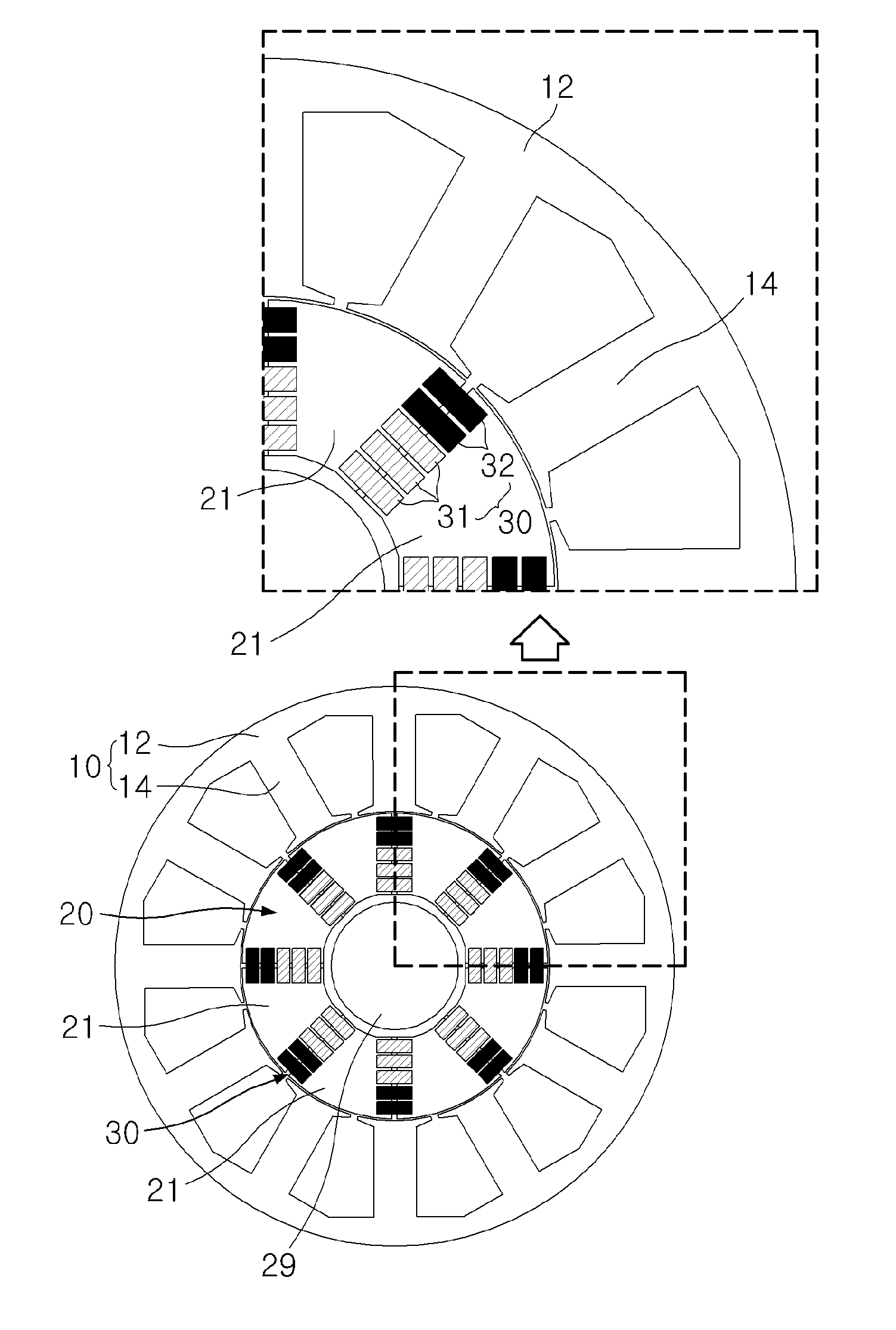
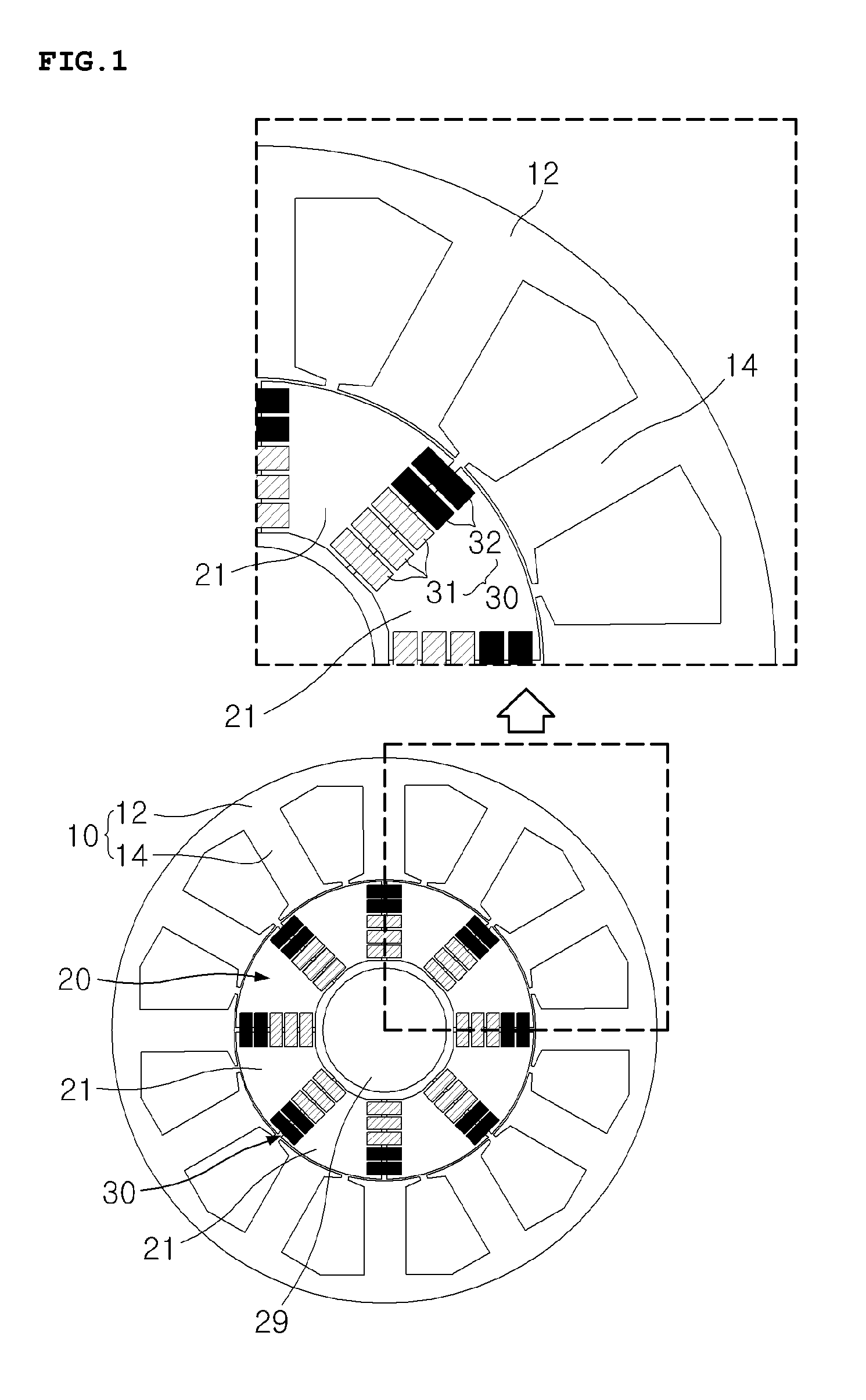
[0032]FIG. 1 is a cross-sectional view showing an interior permanent magnet motor according to the invention, and FIG. 2 is a cross-sectional view showing the interior permanent magnet motor shown in FIG. 1.

[0033]Referring to FIG. 1 and FIG. 2, the interior permanent magnet motor according to the first embodiment of the invention includes a stator 10 having teeth 14, which are wound on a coil (not shown). The interior permanent magnet motor may also include a rotor 20, which is rotatably provided inside the stator 10. The interior permanent magnet motor may also include permanent magnets 30, which are embedded inside the rotor 20. The permanent magnets 30 may include ferrite permanent magnets 31 and rare-earth permanent magnets 32. The ferrite permanent magnets 31 may be barium (Ba) ferrite permanent magnets or strontium (Sr) ferrite permanent magnets. The rare-earth permanent magnets 32 may be samarium-cobalt (Sm—Co) permanent magnets or neodymium (Nd) permanent magnets. The rotor ...

second embodiment

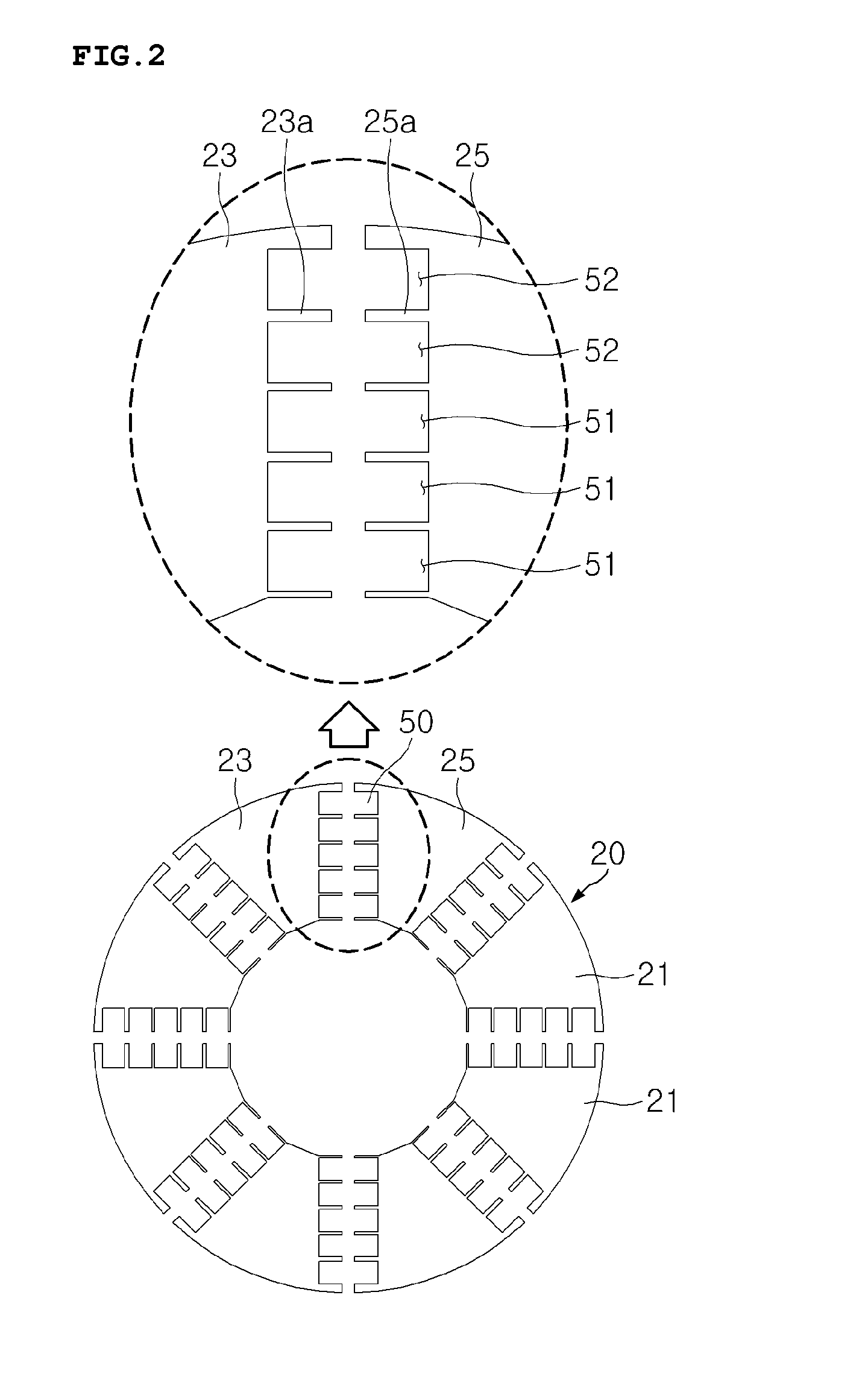
[0042]According to the invention, a plurality of rotor sectors 21 of the rotor 20 is provided integrally. At least two permanent magnet recesses 50 are formed between the rotor sectors 21, and partitions 235 are provided between the permanent magnet recesses 50. Here, a partition 235 is provided between each first rotor sector 23 and each second rotor sector 25, which are adjacent to each other, and both ends of the partition 235 are connected respectively to the first rotor sector 23 and the second rotor sector 25, which are adjacent to each other. That is, one end of the partition 235 is connected to the first rotor sector 23, and the other end of the partition 235 is connected to the second rotor sector 25. Here, it is preferable that the partition 235 be formed integrally with the first rotor sector 23 and the second rotor sector 25. Therefore, the partition 235, the first rotor sector 23 and the second rotor sector 25 may be connected together, and a plurality of rotor sectors ...

third embodiment

[0047]FIG. 5 shows an example of the interior permanent magnet motor according to the invention, in which are formed one first recess 51 with the ferrite permanent magnets 31 being embedded therein and one second recess 52 with the rare-earth permanent magnets 32 being embedded therein. Here, the size of the second recesses 52, which is provided in the outer portion of the rotor 20, is smaller than that of the first recess 51. It is preferable that the size of the rare-earth permanent magnet 32, which is embedded in the rotor 20, be smaller than that of the ferrite permanent magnet 31. Here, the first recess 51 in which the ferrite permanent magnet 31 is embedded is formed in the inner portion of the rotor 20, and the second recess 52 in which the rare-earth permanent magnet 32 is embedded is formed in the outer portion of the rotor 20. In addition, it is preferable that the size of the rare-earth permanent magnet 32 embedded in the outer portion of the rotor 20 be smaller than that...


PUM


Abstract

An interior permanent magnet motor includes a stator having teeth on which a coil is wound, a rotor rotatably provided inside the stator, the rotor including a plurality of rotor sectors, and at least two permanent magnet recesses formed between the rotor sectors. Ferrite permanent magnets are embedded in predetermined ones of the permanent magnet recesses that are formed in an inner portion of the rotor. Rare-earth permanent magnets are embedded in the other ones of the permanent magnet recesses that are formed in an outer portion of the rotor.

Description

TECHNICAL FIELD [0001]The present invention relates, in general, to an interior permanent magnet motor and, more particularly, to an interior permanent magnet motor having magnets embedded inside a rotor.BACKGROUND ART [0002]In general, motors using permanent magnets are divided into surface permanent magnet (SPM) motors, in which magnets are attached to the surface of a rotor, and interior permanent magnet (IPM) motors, in which magnets are embedded inside a rotor. While SPM motors have a complicated structure in order to prevent magnets from flying apart during high-speed rotation, IPM motors do not have such a problem and thus are becoming the major type of motor used.[0003]In IMP motors, the outer portion of the rotor that is adjacent to the stator is more influenced by an armature reaction, and permanent magnets embedded in the outer portion of the rotor are more vulnerable to irreversible demagnetization. In order to prevent the irreversible demagnetization, which occurs in th...

Claims


Application Information

Patent Timeline
IPC IPC(8): H02K1/27H02K1/02
CPCH02K1/02H02K1/2706H02K1/2773H02K2213/03
Inventor KIM, DEOK GEUNCHO, HAN SAMHWANG, KYU YUN
Owner KOMOTEK
Why Eureka
Try Eureka