Touch sensor for non-uniform panels

a touch sensor and non-uniform panel technology, applied in the direction of instruments, using electrical/magnetic means, electric/magnetic measurement arrangements, etc., can solve the problems of low jitter positional data using a regular sensor electrode design, poor snr of the underlying sensor to a touch, and inability to accurately calculate the positional data

Active Publication Date: 2015-01-29
TOUCHNETIX
View PDF1 Cites 46 Cited by
  • Summary
  • Abstract
  • Description
  • Claims
  • Application Information

AI Technical Summary

Benefits of technology

[0022]According to the invention there is provided a two-dimensional capacitive sensor of the mutual-capacitance type comprising a cover panel of varying thickness and an electrode panel arranged under the cover panel, the electrode panel comprising a plurality of transmitter electrodes extending in a first direction and a plurality of receiver electrodes extending in a second direction, wherein an array of sensing nodes is formed between edge portions of the receiver electrodes and adjacent portions of the transmitter electrodes, wherein the length of the edge portions per sensing node is varied with the thickness of the cover panel so that the edge portion length per sensing node increases as the thickness increases, so as to provide part or substantially complete compensation for variation in node sensitivity across the sensor which would otherwise exist as a result of the varying thickness of the cover panel.
[0025]The sensing nodes are formed at an overlap area between crossing portions of the transmitter and receiver electrodes. The crossing portions of the receiver electrodes can be adapted in shape not only to vary the edge portion length with cover panel thickness but also to reduce or substantially eliminate variations in the overlap area caused by varying the edge portion length. In particular, in some embodiments the node overlap area can be kept constant to stop capacitance variation.
[0027]In this first group of embodiments, islands of electrode material can be arranged adjacent the transmitter electrodes and / or the receiver electrodes to reduce visual impact of the transmitter electrodes and / or the receiver electrodes.
[0030]The size of the gap per sensing node can be systematically varied with the thickness of the cover panel in a controlled manner, so that the gap size per sensing node increases as the thickness increases. This approach can be used to contribute to partly or substantially completely compensate for variation in node sensitivity across the sensor.
[0031]In this second group of embodiments, islands of electrode material are arranged in at least some of the gaps between the transmitter and receiver electrodes to reduce visual impact of the transmitter and receiver electrodes.

Problems solved by technology

Of course, in a real world system there are many sources of electrical disturbance that will contaminate the measurements, making them fluctuate.
Equally, a touch sensor that is too sensitive, and tends to respond before the user feels that they have actually contacted the outer lens surface, will often be seen as annoyance as it can tend to give the feeling of responding to “unintended” touches.
A particular challenge arises when the touch sensor is positioned behind a surface that varies substantially in thickness from point to point.
Where it is also desired to place a touch sensor behind such a surface an immediate problem can be seen; the sensitivity will vary dramatically from place-to-place.
One issue that this adaptive method does not address is that at the thickest part of the lens the SNR of the underlying sensor to a touch is relatively poor by virtue of the increased distance from a touching finger to the sensor electrodes.
Hence, computing accurate, low jitter positional data using a regular sensor electrode design is difficult, particularly in high electrical noise environments such as when a portable device incorporating a touch sensor is connected to an external electrical supply, such as to a noisy wall outlet power charger or a wireless charger.
Changing the sensor electrode design to improve the SNR over the entire sensor area will also tend to render the outer edges too sensitive (where the lens is thin) and also somewhat prone to secondary effects such as extreme sensitivity to moisture or sweat.

Method used


Image

  • Touch sensor for non-uniform panels
  • Touch sensor for non-uniform panels
  • Touch sensor for non-uniform panels

Examples


application examples

General Points & Application Examples

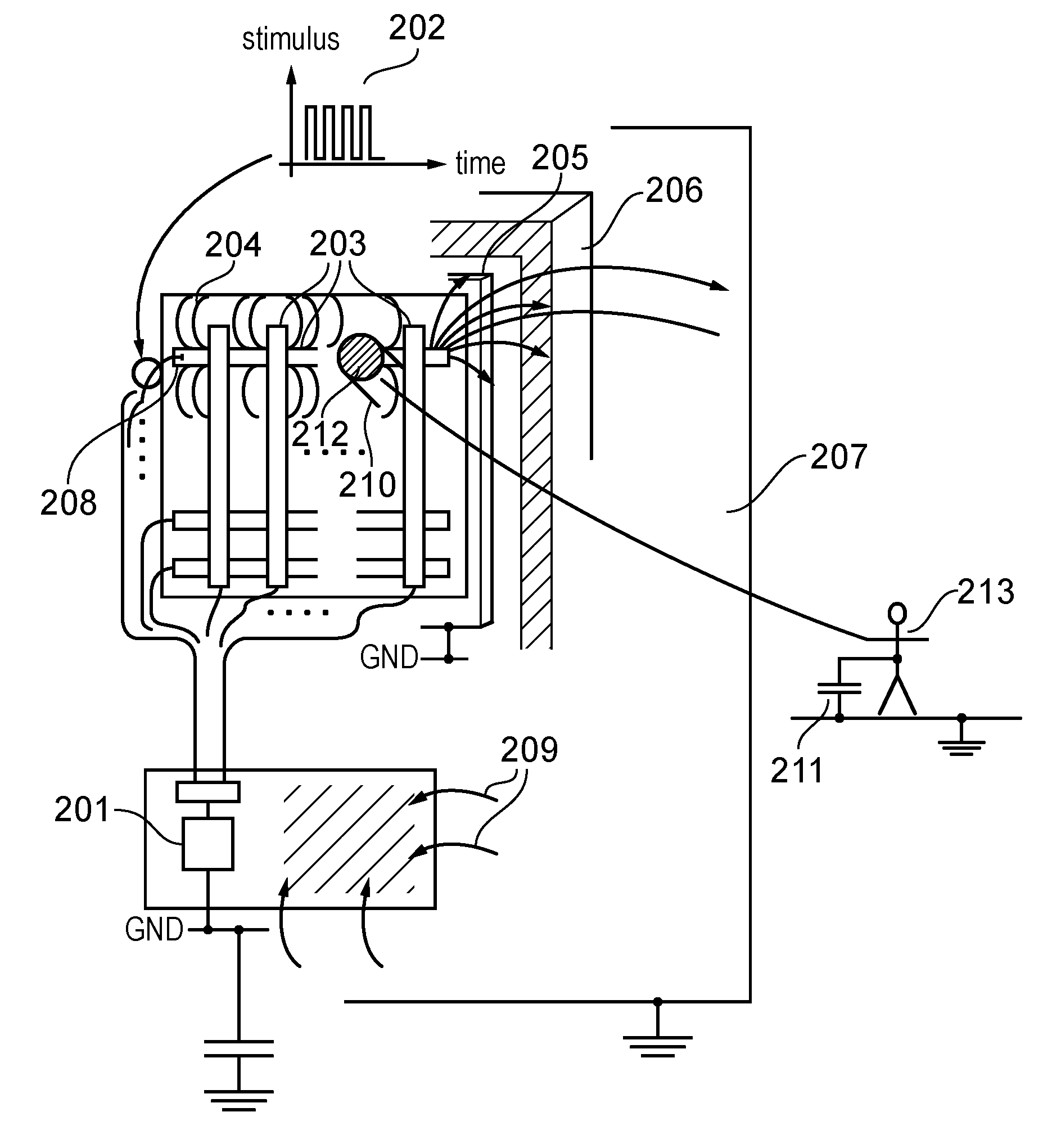
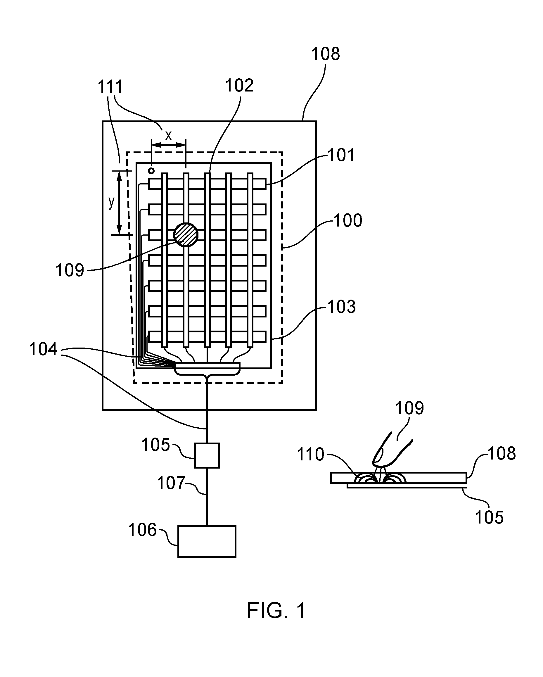
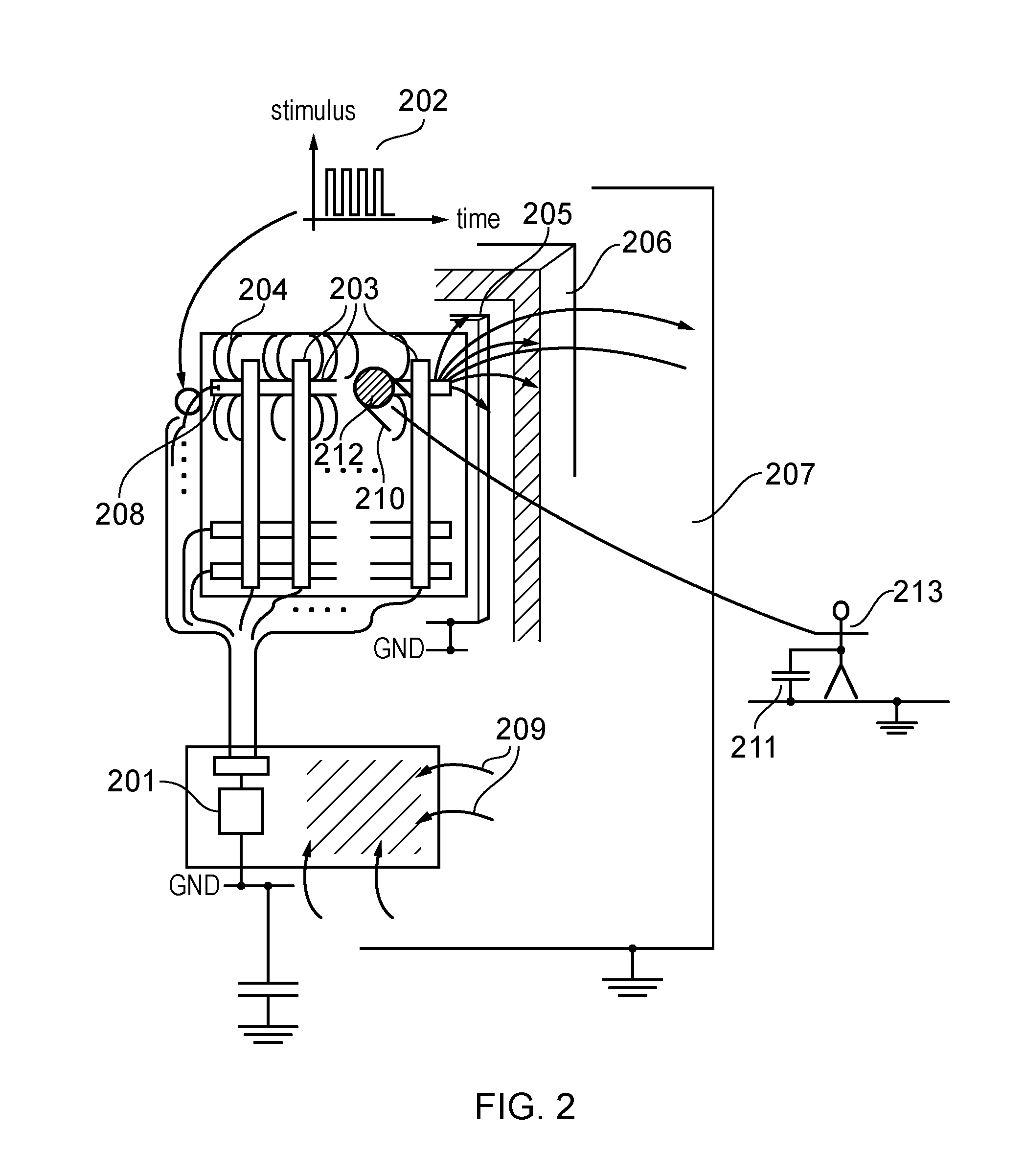
[0077]It will be understand that the general prior art structures and features described in relation to FIGS. 1 to 4, such as a host processing system, a communication interface 107 and a controller chip, may be incorporated in devices, systems and sub-systems embodying the invention. Moreover, in touch screen embodiments it will be understood that a planar display, such as a liquid crystal display or a light emitting diode display will be arranged under the touch sensor.

[0078]It will be appreciated that the sensor according to embodiments of the invention is applicable to many types of device / appliance. For example, sensors can be used with ovens, grills, washing machines, tumble-dryers, dish-washers, microwave ovens, food blenders, bread makers, drinks machines, computers, home audiovisual equipment, personal computers, portable media players, PDAs, cell phones, computers, games consoles and so forth.

[0079]In some cases, variations in the cover...


PUM


Abstract

A two-dimensional capacitive touch sensor having a cover layer of varying thickness arranged on top of its electrode structure. An array of sensing nodes is formed between edge portions of the receiver electrodes and adjacent portions of the transmitter electrodes. To compensate for the varying thickness of the cover layer, the length of the edge portions per sensing node is varied to equalize node sensitivity across the sensor and thus suppress the systematic variation in node sensitivity which would otherwise arise as a result of the varying thickness of the cover layer.

Description

BACKGROUND OF THE INVENTION[0001]The present invention relates to the field of two-dimensional capacitive touch sensors including touch screens and touch pads and their associated sensor and controller chip. In particular, it relates to the specific design of the electrode patterns used to create a physical sensor suitable to sense the presence of one or more touching objects when the sensor is situated behind, or is embedded in, an insulating cover material that is non-uniform in its thickness.[0002]A capacitive touch sensor can be generalised as one that uses a physical sensor element comprising an arrangement of electrically conductive electrodes extending over a touch sensitive area and a controller chip connected to the electrodes and operable to measure changes in the electrical capacitance of each of the electrodes or the mutual capacitance between combinations of the electrodes.[0003]FIG. 1 shows principal components of a generic capacitive touchscreen. Item 100 represents t...

Claims


Application Information

Patent Timeline
Patent Type & Authority Applications(United States)
IPC IPC(8): G01B7/00G01B7/14G06F3/044
CPCG01B7/003G01B7/14G06F3/044G06F3/0443G06F3/0446G06F3/03547
Inventor SLEEMAN, PETER
Owner TOUCHNETIX
Why Eureka
Try Eureka