Ink jet recording apparatus

a recording apparatus and ink jet technology, applied in the direction of printing, other printing apparatus, etc., can solve the problems of smearing or blurring of the surface of the recording medium, plural ink dot array characters, etc., and achieve the effect of preventing the smearing of ink that lands on the recording medium

Active Publication Date: 2015-01-29
MIMAKI ENG
View PDF2 Cites 18 Cited by
  • Summary
  • Abstract
  • Description
  • Claims
  • Application Information

AI Technical Summary

Benefits of technology

[0016]According to the disclosed ink jet recording apparatus, the smearing of ink that lands on a recording medium can be prevented, and the ink can be completely dried even in a case where a hard-to-dry ink is used such as an ink which is composed of an aqueous ink vehicle containing latex as a binder resin, a case where a recording speed is high, or a case where a non-absorbent recording medium which is not coated with a coating agent as an ink absorbing layer is used. In addition, since nozzles of a recording head can be prevented from being dried, a problem of ink non-discharge caused by the drying of the nozzles can be solved.

Problems solved by technology

In an ink jet recording apparatus in which an ink containing an organic solvent as a major component is ejected, there is a problem in that images or characters composed of plural ink dot arrays which are printed onto a surface of a recording medium are smeared or blurred by, for example, the ejected ink droplets widely infiltrating into the recording medium around ink-landing positions.

Method used


Image

  • Ink jet recording apparatus
  • Ink jet recording apparatus
  • Ink jet recording apparatus

Examples


first embodiment

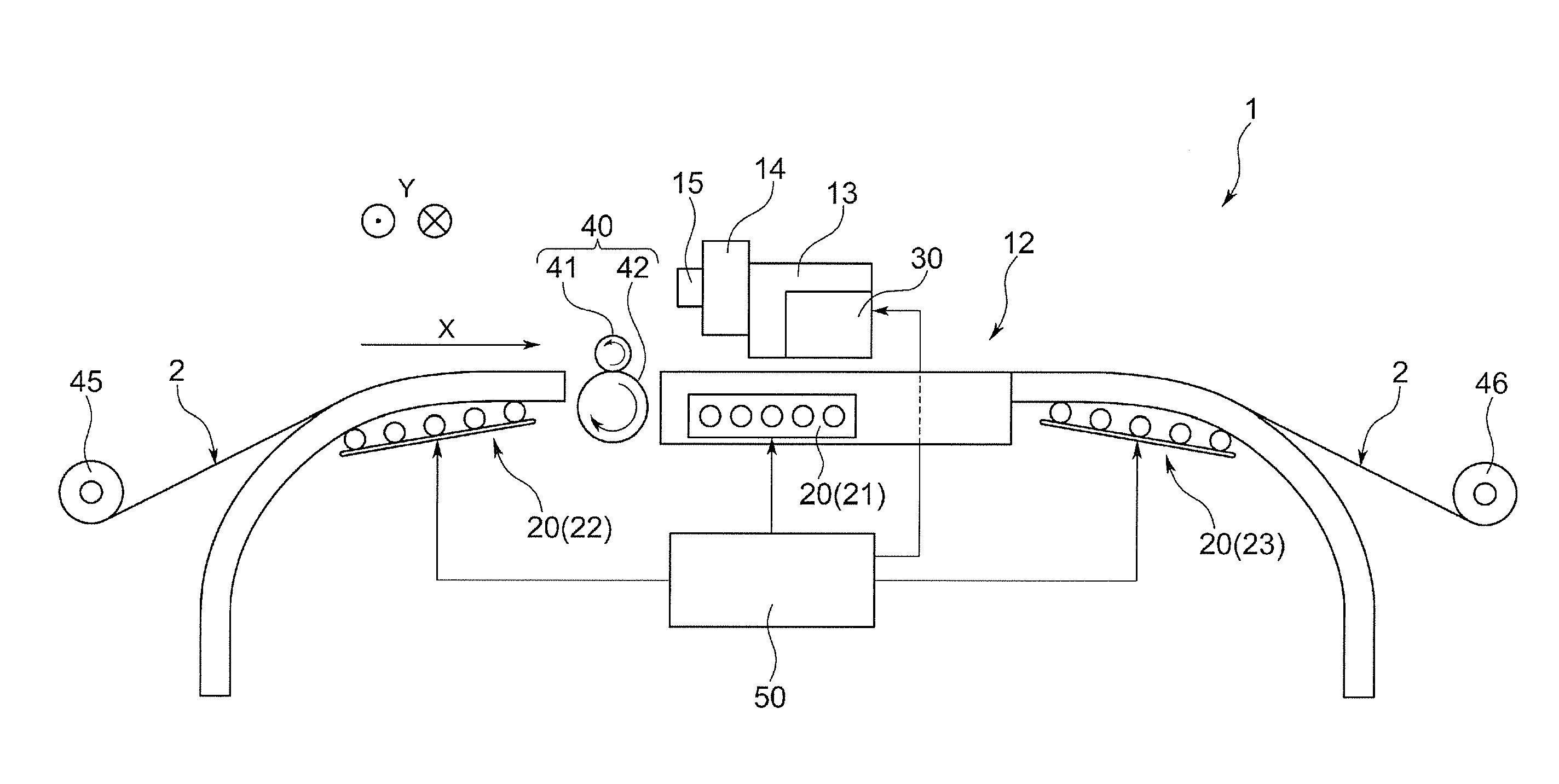
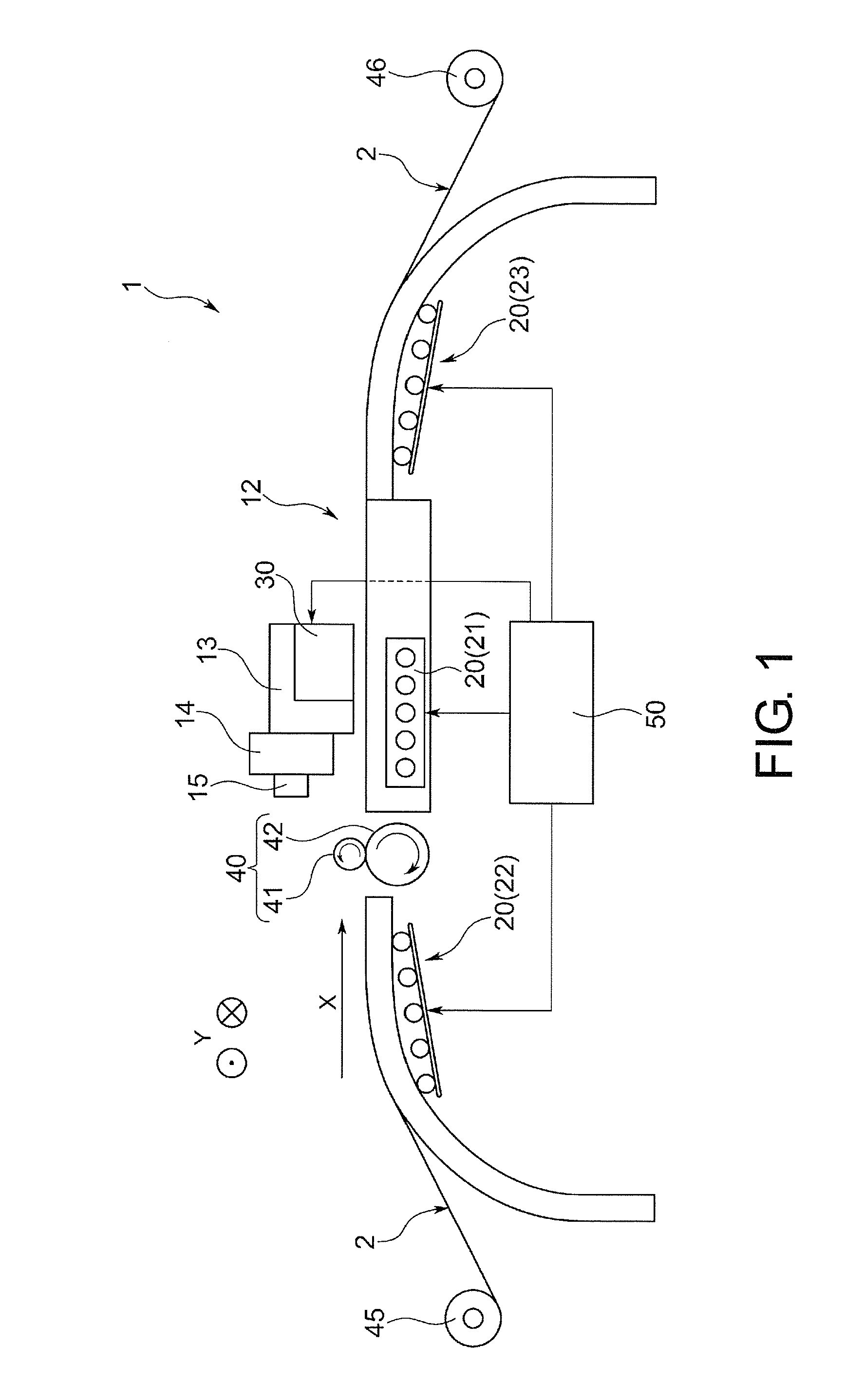
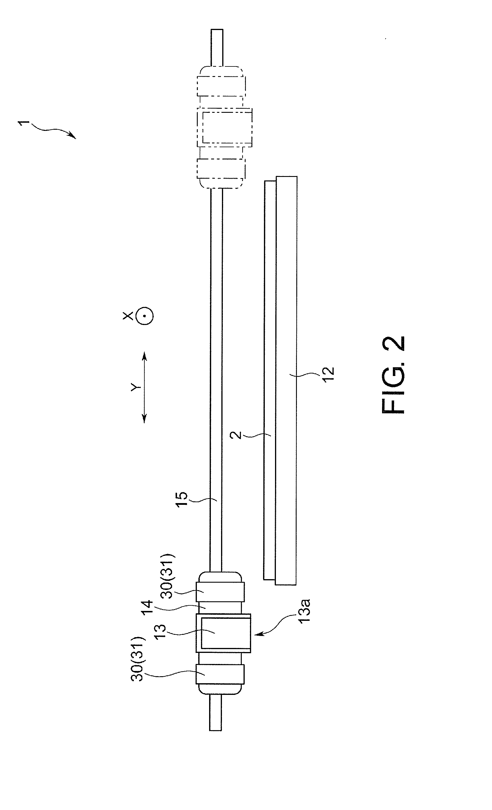
[0025]FIGS. 1 and 2 are schematic diagrams illustrating a configuration example of an ink jet recording apparatus 1 according to a first embodiment of the present invention, in which FIG. 1 is a diagram illustrating the ink jet recording apparatus 1 when seen from a direction (Y direction in the drawing) perpendicular to a moving direction (X direction in the drawing) of a recording medium, and FIG. 2 is a diagram illustrating the ink jet recording apparatus 1 when seen from the moving direction (X direction in the drawing) of the recording medium.

[0026]The ink jet recording apparatus 1 according to the embodiment includes: a platen (support body) 12 that supports a recording medium 2; a recording head 13 that ejects ink from plural discharge ports onto a surface of the recording medium 2 to land thereon while reciprocating in the direction (Y direction) perpendicular to the moving direction of the recording medium 2; a carriage 14 on which the recording head 13 is mounted and that ...

second embodiment

[0063]Next, an ink jet recording apparatus 1 according to a second embodiment of the present invention will be described.

[0064]The ink jet recording apparatus 1 according to the second embodiment has the same basic configuration as that of the ink jet recording apparatus 1 according to the first embodiment and has different points therefrom particularly in a configuration of the heating means. Hereinafter, the embodiment will be described focusing on the different points.

[0065]As illustrated in FIG. 3, in the embodiment, as the carriage heater 30 included in the heating means, both the infrared heater 31 and a warm-air heater 32 are provided at each of both ends of the recording head 13 mounted on the carriage 14. Although not illustrated, the platen heater 20 that heats the recording medium 2 from the back surface of the recording medium 2 is also provided similarly to the above-described first embodiment.

[0066]Hereinafter, a configuration example of the warm-air heater 32 will be ...

third embodiment

[0079]Next, an ink jet recording apparatus 1 according to a third embodiment of the present invention will be described.

[0080]The ink jet recording apparatus 1 according to the third embodiment has the same basic configuration as that of the ink jet recording apparatus 1 according to the second embodiment and has different points therefrom particularly in a configuration of the infrared heater 31 as the carriage heater 30. Hereinafter, the embodiment will be described focusing on the different points.

[0081]As illustrated in FIG. 5A, in the embodiment, as the carriage heater 30 included in the heating means, two pairs of the infrared heaters 31 and the warm-air heaters 32 are provided. In the embodiment, unlike the above-described second embodiment, the infrared heaters 31 mounted on the carriage 14 are disposed to be distant from the recording head 13 in the moving direction (X direction in the drawing) of the recording medium 2. More specifically, the infrared heaters 31 are dispos...


PUM


Abstract

Disclosed is an ink jet recording apparatus that prints an image onto a recording medium using an ink which is composed of an aqueous ink vehicle containing latex as a binder resin. The ink jet recording apparatus includes a carriage on which a recording head for discharging ink droplets onto the recording medium is mounted and that moves relative to the recording medium, in which an infrared heater that is disposed opposite to the recording medium and heats the recording medium is mounted on the carriage, and the infrared heater is disposed to be distant from the recording head in a moving direction (X direction) of the recording medium.

Description

TECHNICAL FIELD[0001]The present invention relates to an ink jet recording apparatus and specifically relates to an ink jet recording apparatus which records images or characters composed of plural ink dot arrays onto a recording medium by ejecting ink thereon.BACKGROUND ART[0002]In an ink jet recording apparatus in which an ink containing an organic solvent as a major component is ejected, there is a problem in that images or characters composed of plural ink dot arrays which are printed onto a surface of a recording medium are smeared or blurred by, for example, the ejected ink droplets widely infiltrating into the recording medium around ink-landing positions.[0003]As a technique to solve such a problem, an ink jet recording apparatus is known, the ink jet recording apparatus including a heater for heating a recording medium, in which the smearing of ink droplets that land on a surface of a recording medium is prevented by drying the ink droplets at an early stage (refer to Paten...

Claims


Application Information

Patent Timeline
Patent Type & Authority Applications(United States)
IPC IPC(8): B41J11/00B41J2/01
CPCB41J2/01B41J11/0015B41J11/00216B41J11/0022B41J11/0024B41J11/00242B41J11/00244
Inventor OHNISHI, MASARU
Owner MIMAKI ENG
Why Eureka
Try Eureka