Rounded blade scissors

a scissors and rounded technology, applied in the field of rounded blade scissors, can solve the problems of user injury, out-of-order motors, nose hair trimmers, etc., and achieve the effects of convenient cutting, increased time efficiency, and reduced possibility of user injury

Inactive Publication Date: 2015-02-05
KIM JEONG PYO
View PDF20 Cites 3 Cited by
  • Summary
  • Abstract
  • Description
  • Claims
  • Application Information

AI Technical Summary

Benefits of technology

[0029]As described above, the rounded blade scissors according to the preferred embodiments of the present invention provides the following effects.
[0030]First, differently from the cutting blades of the conventional scissors, the scissors according to the present invention provide annular cutting blades so as to reduce possibility that the user is injured.
[0031]Second, the user has to rotate the conventional scissors perpendicularly, but the scissors according to the present invention provide convenience in cutting because the cutting blades provide a motion direction which is perpendicular to a motion direction of hand-grips of the scissors.
[0032]Third, differently from the cutting blades of the conventional scissors, the scissors according to the present invention provide annular cutting blades, so that the user can uniformly cut a target.
[0033]Fourth, differently from the cutting blades of the conventional scissors, the scissors according to the present invention provide annular cutting blades, so that it increases time efficiency because the user does not need to observe his or her nostrils with a mirror while cutting the nose hair.
[0034]Fifth, because the cutting blades provide a motion direction which is perpendicular to a motion direction of hand-grips of the scissors, when there is a need to cut the target perpendicularly to the direction of the cutting blades of the conventional scissors, the scissors according to the present invention can be applied to operating scissors for medical use or scissors with other purposes.

Problems solved by technology

Conventionally, people used relatively small scissors which can be inserted into the nose, but such scissors have a problem in that the user may be injured by the cutting blade of the scissors.
However, such nose hair trimmers have a disadvantage in that nose hair is inserted into the trimmer or a battery or a motor is out of order.
Moreover, because the nose hair is cut irregularly according to the form of the cutting blade of the trimmer, it is difficult to cut the nose hair of a wanted portion in a balanced way.
Meanwhile, the scissors having the rounded front end portion of the cutting blade has a disadvantage in that it may injure the inside of the nose because only the front end portion is formed round.
Therefore, the conventional scissors also has a limitation in trimming the nose hair uniformly and conveniently.
So, because the user has to trim the nose hair little by little while paying a careful attention and has to observe his or her nostrils using a mirror, it takes much time to trim the nose hair.
Moreover, the conventional scissors is very inconvenient because the user has to manipulate the scissor while perpendicularly rotating the scissors in order to effectively cut the nose hair.

Method used


Image

  • Rounded blade scissors
  • Rounded blade scissors
  • Rounded blade scissors

Examples


first embodiment

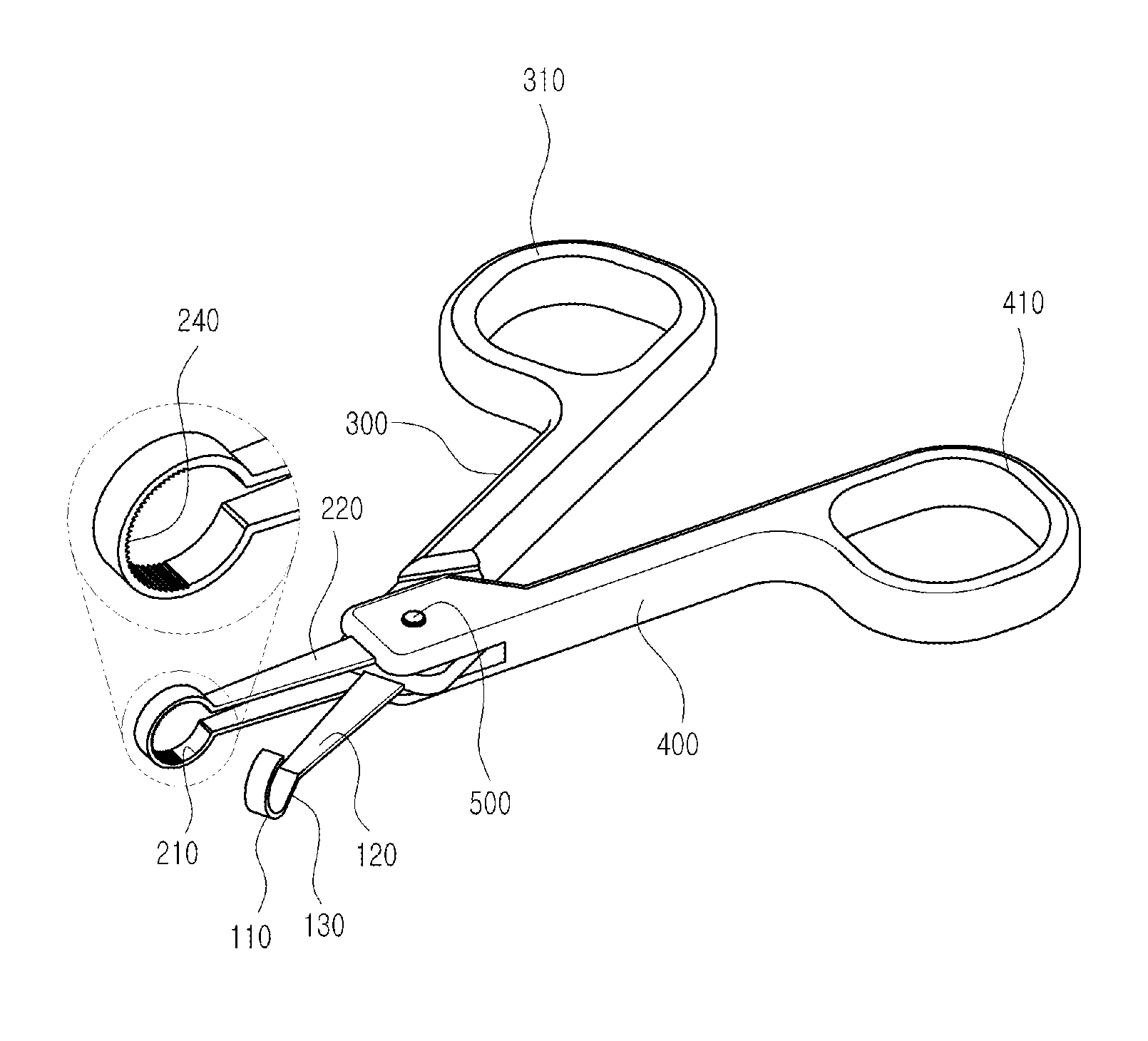
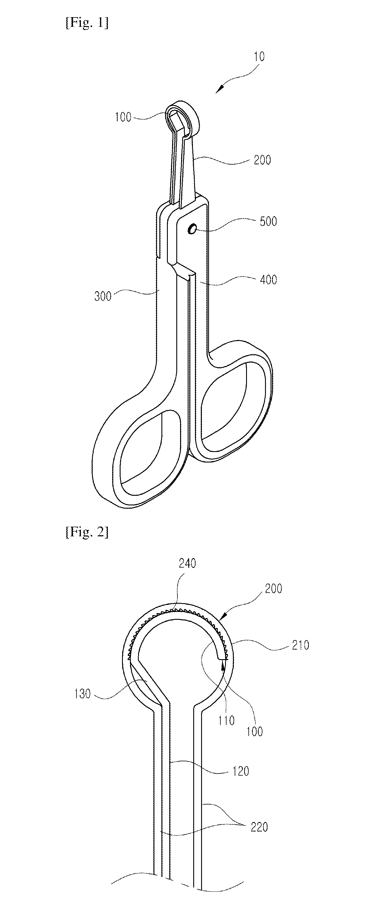
[0086]The first cutting blade 110 according to the first preferred embodiment of the present invention is formed in a hook which is bent roundly with a predetermined curvature, and the second cutting blade 210 is formed in a closed annular shape so as to surround the outer circumferential surface of the first cutting blade 110. As shown in FIG. 2, in the case that the first cutting blade 110 is in contact with the second cutting blade 210, the first cutting blade 110 is close to the bottom of the second cutting blade 210 of the annular shape.

[0087]The contact preventing means 130 according to the first preferred embodiment of the present invention is located between the first cutting blade 110 and the first supporter 120. When the outer circumferential surface of the first cutting blade 110 comes in contact with the inner circumferential surface of the second cutting blade 210, the contact preventing means 130 is bent from the outer circumferential surface of the first cutting porti...

second embodiment

[0094]The cutting blade 111 according to the second preferred embodiment of the present invention is formed in a hook and the second cutting blade 211 is formed in a closed annular shape. When the first cutting blade 111 comes into contact with the second cutting blade 211, the outer circumferential surface of the first cutting blade 111 comes into contact with the inner circumferential surface of the second cutting blade 211 in the same way as the first preferred embodiment.

[0095]As shown in FIG. 7, the contact preventing means 230 of the second preferred embodiment is located between the second cutting blade 211 and the second supporter 221, and has a separation groove recessed from the inner circumferential surface of the second cutting portion 200 in a direction of the outer circumferential surface. That is, the contact preventing means 230 separates a portion of the second cutting portion 200 from the first cutting portion 100 when the outer circumferential surface of the first...

third embodiment

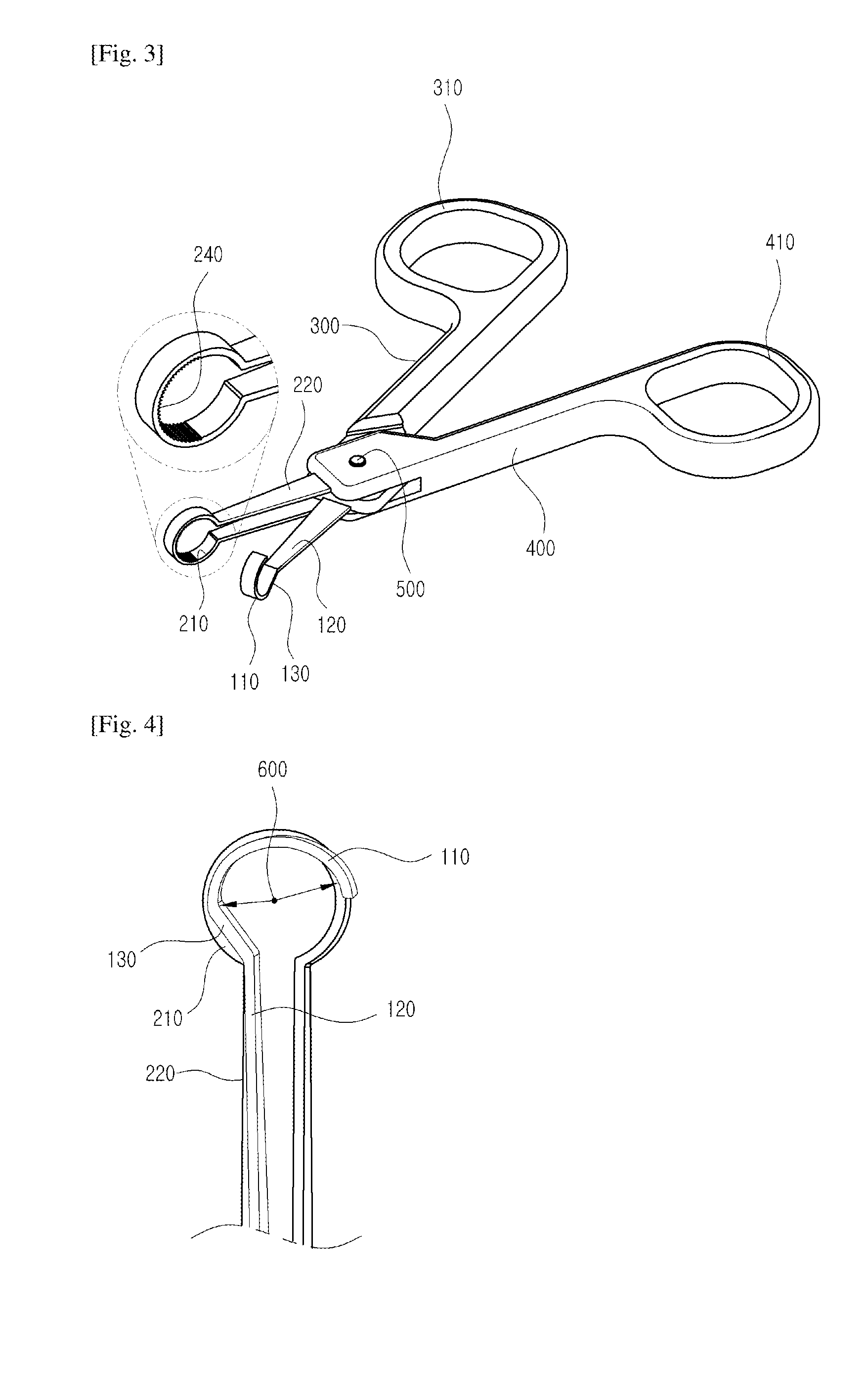
[0097]The cutting blade 112 according to the third preferred embodiment of the present invention is formed in a closed annular shape, and the second cutting blade 212 is formed in a hook. As shown in FIG. 8, in the case that the first cutting blade 112 is in contact with the second cutting blade 212, the first cutting blade 112 is close to the bottom of the hook-shaped second cutting blade 212, such that the outer circumferential surface of the first cutting blade 112 comes into contact with the inner circumferential surface of the second cutting blade 212.

[0098]As shown in FIG. 9, the second cutting blade 212 is formed in such a manner that a straight distance from a central point 600 of the first cutting blade 112 to the second cutting blade 212 is gradually reduced from the second supporter 222 to the second cutting blade212.

[0099]The contact preventing means 131 according to the third preferred embodiment of the present invention is located between the first cutting blade 112 an...


PUM


Abstract

The present invention relates to rounded blade scissors. The rounded blade scissors according to one embodiment of the present invention comprise: a first cutting portion including a first cutting blade bent in one direction to cut a target; a second cutting portion including a second cutting blade having a closed annular or polygonal shape to surround the surface of the first cutting portion; a first frame portion supporting the first cutting portion on one side of the first cutting portion; a second frame portion supporting the second cutting portion on one side of the second cutting portion; and a coupling portion that hingedly couples the first frame portion with the second frame portion so that the first cutting portion comes into contact with the second frame portion through rotation. Therefore, the cutting can be performed in a safe and effective manner. According to the present invention, the cutting target can be cut in an easy, convenient, and safe manner.

Description

TECHNICAL FIELD[0001]The present invention relates to rounded blade scissors.BACKGROUND ART[0002]In general, people use nose hair trimmers or nose hair scissors in order to trim nose hair. Because a cutting blade part of such a tool directly abuts against the inside of the nose, the cutting blade part must be formed in such a way as to cut the nose hair without injuring the human body.[0003]Moreover, because the nose hair is formed according to the internal shape of the nose, a rounded blade is provided to trim the nose hair uniformly.[0004]Conventionally, people used relatively small scissors which can be inserted into the nose, but such scissors have a problem in that the user may be injured by the cutting blade of the scissors.[0005]Recently, in order to solve the problem, as tools for trimming nose hair, automatic nose hair trimmers and scissors having rounded front end portion of a cutting blade have been developed, and such technologies are disclosed in Korean Patent Laid-open...

Claims


Application Information

Patent Timeline
Patent Type & Authority Applications(United States)
IPC IPC(8): B26B13/06
CPCB26B13/06B26B13/28
Inventor KIM, JEONG PYO
Owner KIM JEONG PYO
Why Eureka
Try Eureka