Wide-Angled Wrench

a wrench and wide-angle technology, applied in the field of hand tools, can solve problems such as inconvenience for users, and achieve the effect of wide-angle wrenches

Inactive Publication Date: 2015-02-05
YANG CHUNG CHENG +1
View PDF4 Cites 10 Cited by
  • Summary
  • Abstract
  • Description
  • Claims
  • Application Information

AI Technical Summary

Benefits of technology

[0007]According to the primary advantage of the present invention, the positioning projection of the first one of the elastic plates is selectively positioned in one of the first positioning grooves of the first pivot portion of the handle, and the positioning projection of the second one of the elastic plates is selectively positioned in one of the second positioning grooves of the second pivot portion of the tool head, so that the angles of the handle and the tool head relative to the connector can be changed to freely adjust the working angles of the wide-angled wrench, thereby facilitating the wide-angled wrench being operated in a narrower working zone.
[0008]Further benefits and advantages of the present invention will become apparent after a careful reading of the detailed description with appropriate reference to the accompanying drawings.BRIEF DESCRIPTION OF THE SEVERAL VIEWS OF THE DRAWING(S)
[0009]FIG. 1 is an exploded perspective view of a wide-angled wrench in accordance with the preferred embodiment of the present invention.
[0010]FIG. 2 is a top cross-sectional assembly view of the wide-angled wrench as shown in FIG. 1.
[0011]FIG. 3 is a cross-sectional view of the wide-angled wrench taken along line 3-3 as shown in FIG. 3.
[0012]FIG. 4 is a perspective assembly view of the wide-angled wrench as shown in FIG. 1.

Problems solved by technology

However, the conventional wrench has a fixed structure so that the working angles of the handle and the tool head cannot be adjusted freely, and the conventional wrench cannot be easily operated in a narrow working zone, such as an engine room and the like, thereby greatly causing inconvenience to the user when operating the conventional wrench in the narrow working zone.

Method used


Image

  • Wide-Angled Wrench
  • Wide-Angled Wrench
  • Wide-Angled Wrench

Examples


Embodiment Construction

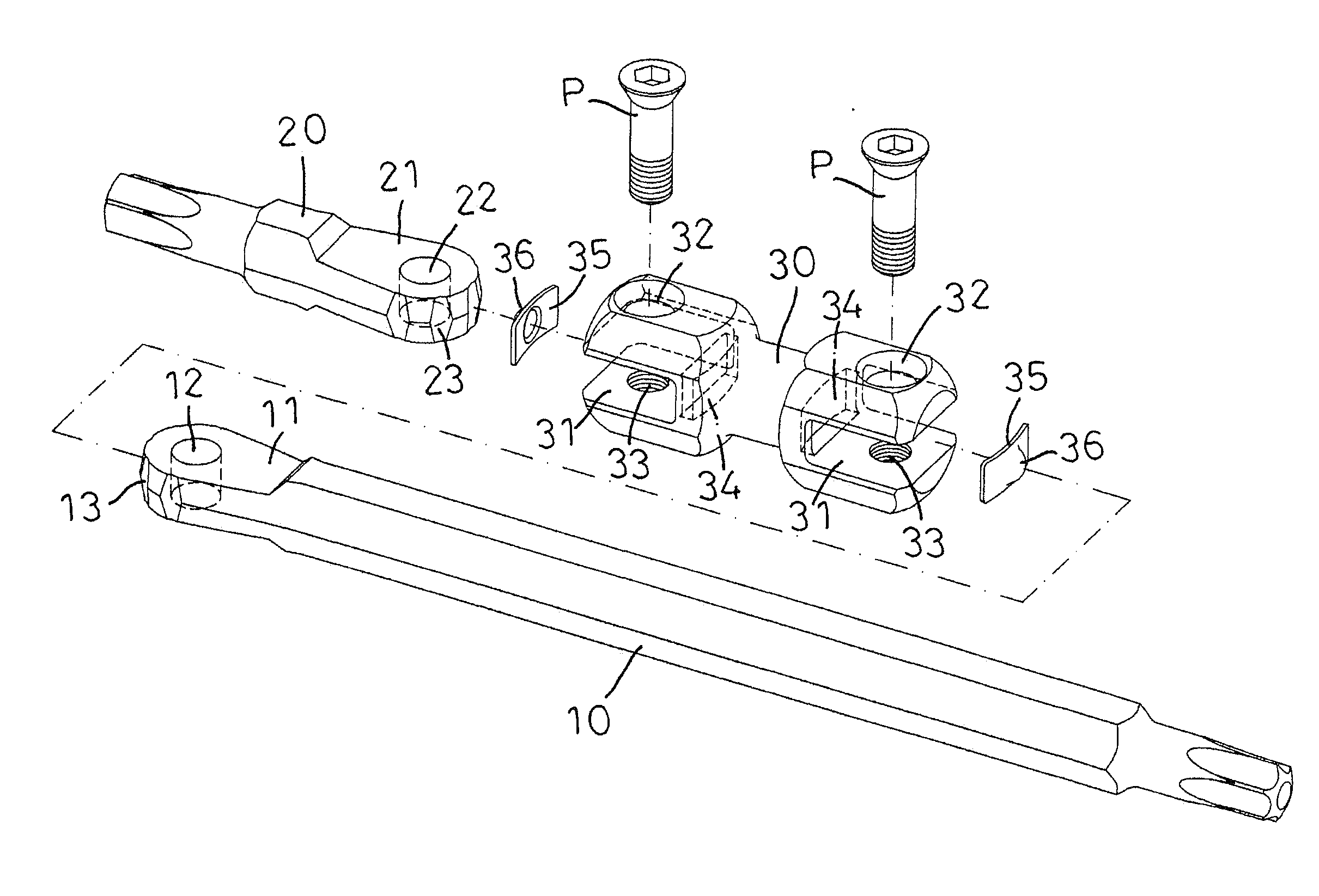
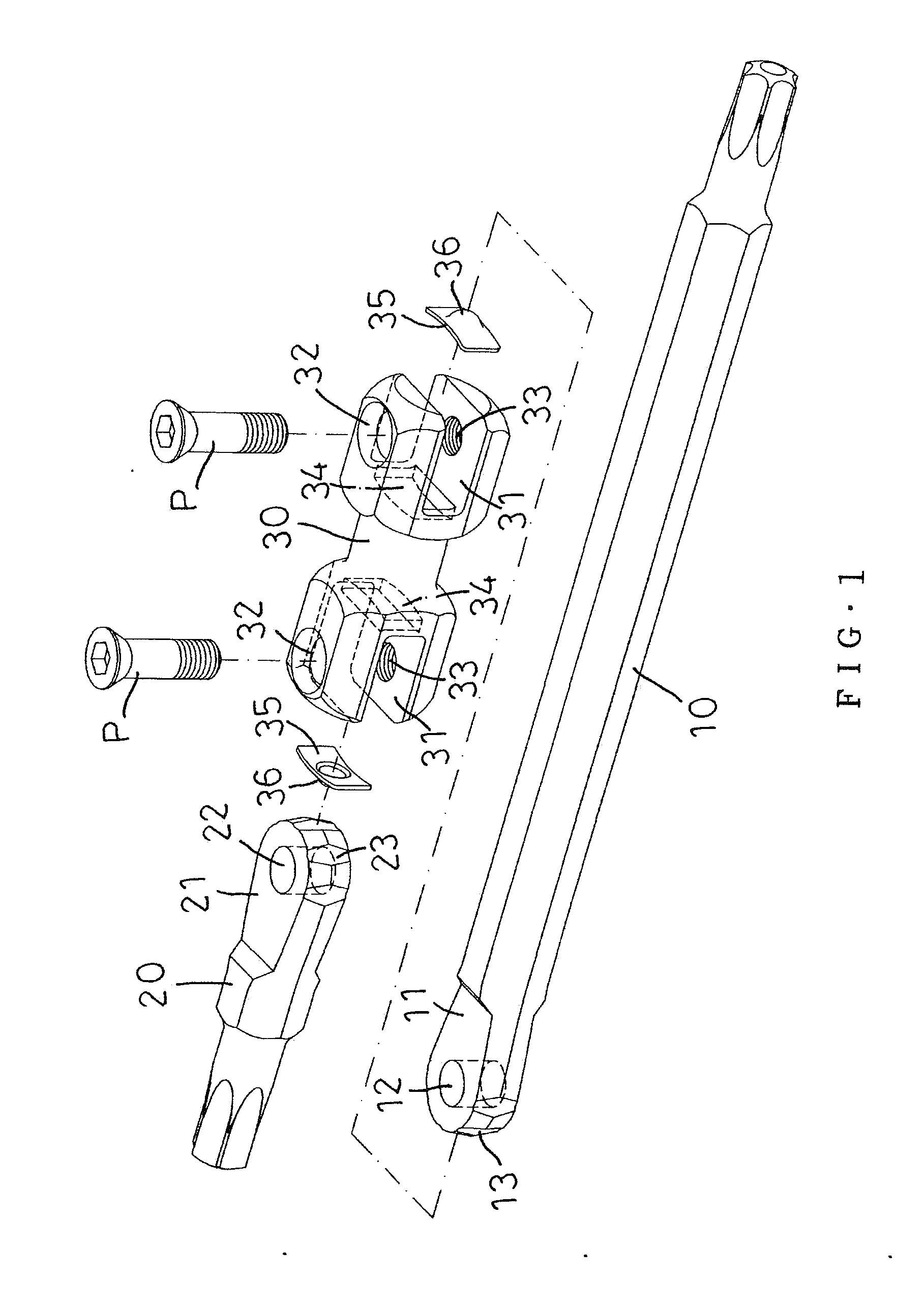
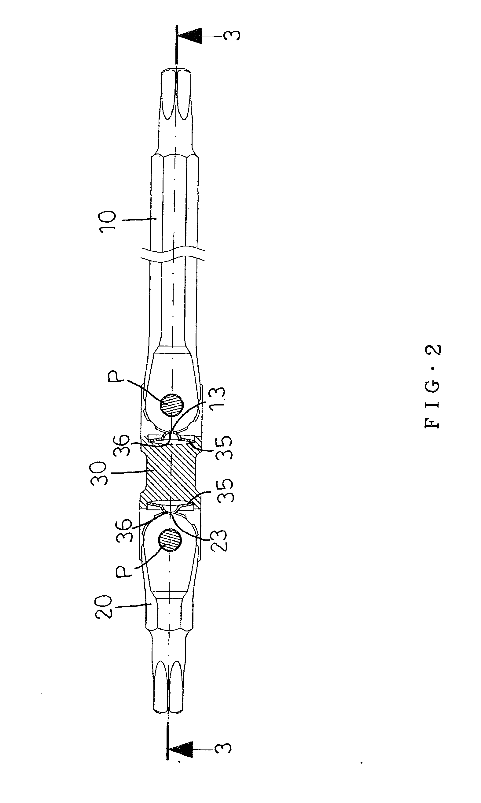
[0021]Referring to the drawings and initially to FIGS. 1-7, a wide-angled wrench in accordance with the preferred embodiment of the present invention comprises a handle 10, a connector 30 connected with the handle 10, and a tool head 20 connected with the connector 30.

[0022]The connector 30 is provided with two mounting channels 31 formed on two opposite ends thereof Each of the mounting channels 31 of the connector 30 has a substantially U-shaped profile and is provided with a through hole 32, a screw hole 33 and a receiving recess 34.

[0023]The handle 10 has an end provided with a substantially semi-circular first pivot portion 11 mounted in a first one of the mounting channels 31 of the connector 30. The first pivot portion 11 of the handle 10 is provided with a first pivot hole 12. The first pivot portion 11 of the handle 10 has an arcuate face provided with a plurality of first positioning grooves 13.

[0024]The tool head 20 has an end provided with a substantially semi-circular s...


PUM


Abstract

A wide-angled wrench includes a handle, a connector, and a tool head. The connector is provided with two mounting channels each provided with a receiving recess. The handle has a first pivot portion provided with a plurality of first positioning grooves. The tool head has a second pivot portion provided with a plurality of second positioning grooves. The wide-angled wrench further comprises two elastic plates mounted in the receiving recess of each of the mounting channels. Each of the elastic plates is provided with a positioning projection. The positioning projection of a first one of the elastic plates is positioned in one of the first positioning grooves of the handle. The positioning projection of a second one of the elastic plates is positioned in one of the second positioning grooves of the tool head.

Description

CROSS-REFERENCES TO RELATED APPLICATIONS[0001]The present invention is a continuation-in-part application of the co-pending U.S. Ser. No. 13 / 310,842.BACKGROUND OF THE INVENTION[0002]1. Field of the Invention[0003]The present invention relates to a hand tool and, more particularly, to a wide-angled wrench whose working angles can be adjusted.[0004]2. Description of the Related Art[0005]A conventional wrench comprises a handle and a tool head. Thus, the conventional wrench is used to drive and rotate a screw member, such as a screw, nut, bolt and the like. However, the conventional wrench has a fixed structure so that the working angles of the handle and the tool head cannot be adjusted freely, and the conventional wrench cannot be easily operated in a narrow working zone, such as an engine room and the like, thereby greatly causing inconvenience to the user when operating the conventional wrench in the narrow working zone.BRIEF SUMMARY OF THE INVENTION[0006]In accordance with the pre...

Claims


Application Information

Patent Timeline
Patent Type & Authority Applications(United States)
IPC IPC(8): B25B23/00
CPCB25B23/0035B25B23/0028B25G1/063B25B13/481
Inventor YANG, CHUNG-CHENGYANG, HSIN-HUNG
Owner YANG CHUNG CHENG
Why Eureka
Try Eureka