Screen printer, and method of cleaning a stencil of a screen printer

Active Publication Date: 2015-02-05
ASMPT SINGAPORE PTE LTD
View PDF10 Cites 8 Cited by
  • Summary
  • Abstract
  • Description
  • Claims
  • Application Information

AI Technical Summary

Benefits of technology

[0009]The cleaning device may include a paper cleaning module for cleaning the selected apertures. The paper cleaning module may be configur

Problems solved by technology

However, current cleaning methods tend to be relatively inefficient, take an un

Method used


Image

  • Screen printer, and method of cleaning a stencil of a screen printer
  • Screen printer, and method of cleaning a stencil of a screen printer
  • Screen printer, and method of cleaning a stencil of a screen printer

Examples


Embodiment Construction

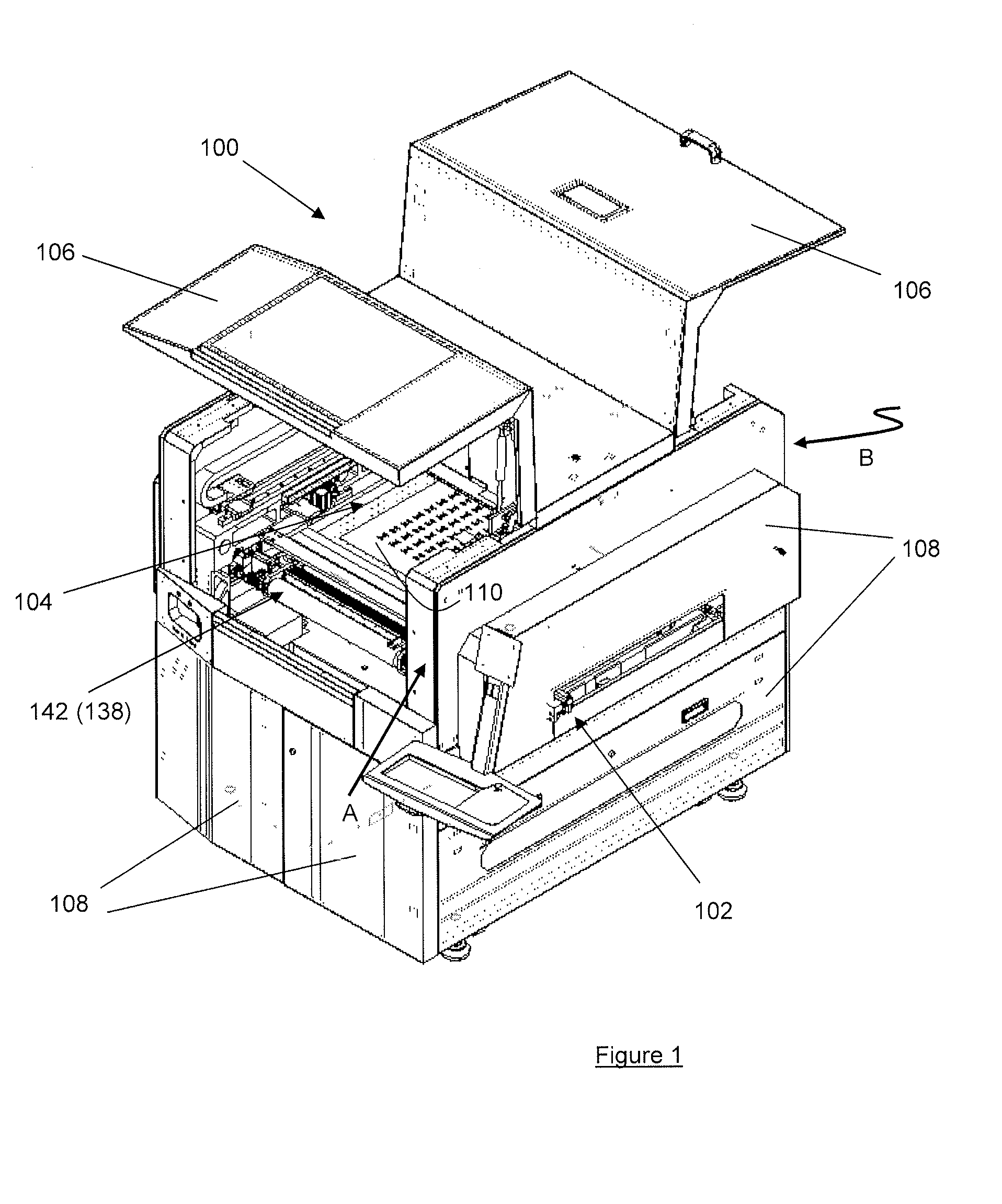
[0027]FIG. 1 is a perspective view of an SMT screen printer 100 comprising a conveyor system 102 for conveying substrates such as PCBs (not shown) into a printing chamber 104 of the screen printer 100. The screen printer 100 includes a pair of pivotable covers 106, shown in open positions in FIG. 1, to allow access to the printing chamber 104 and the pair of pivotable covers 106 is normally closed during operation of the screen printer 100. The screen printer 100 further includes a number of protective panels 108.

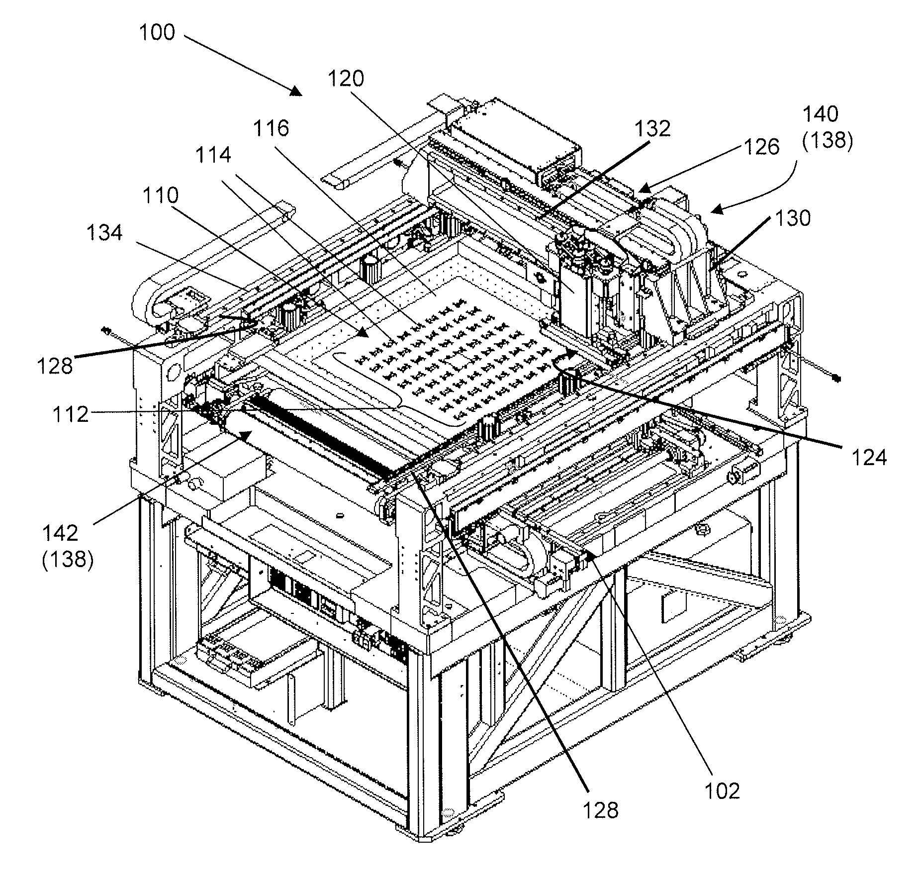
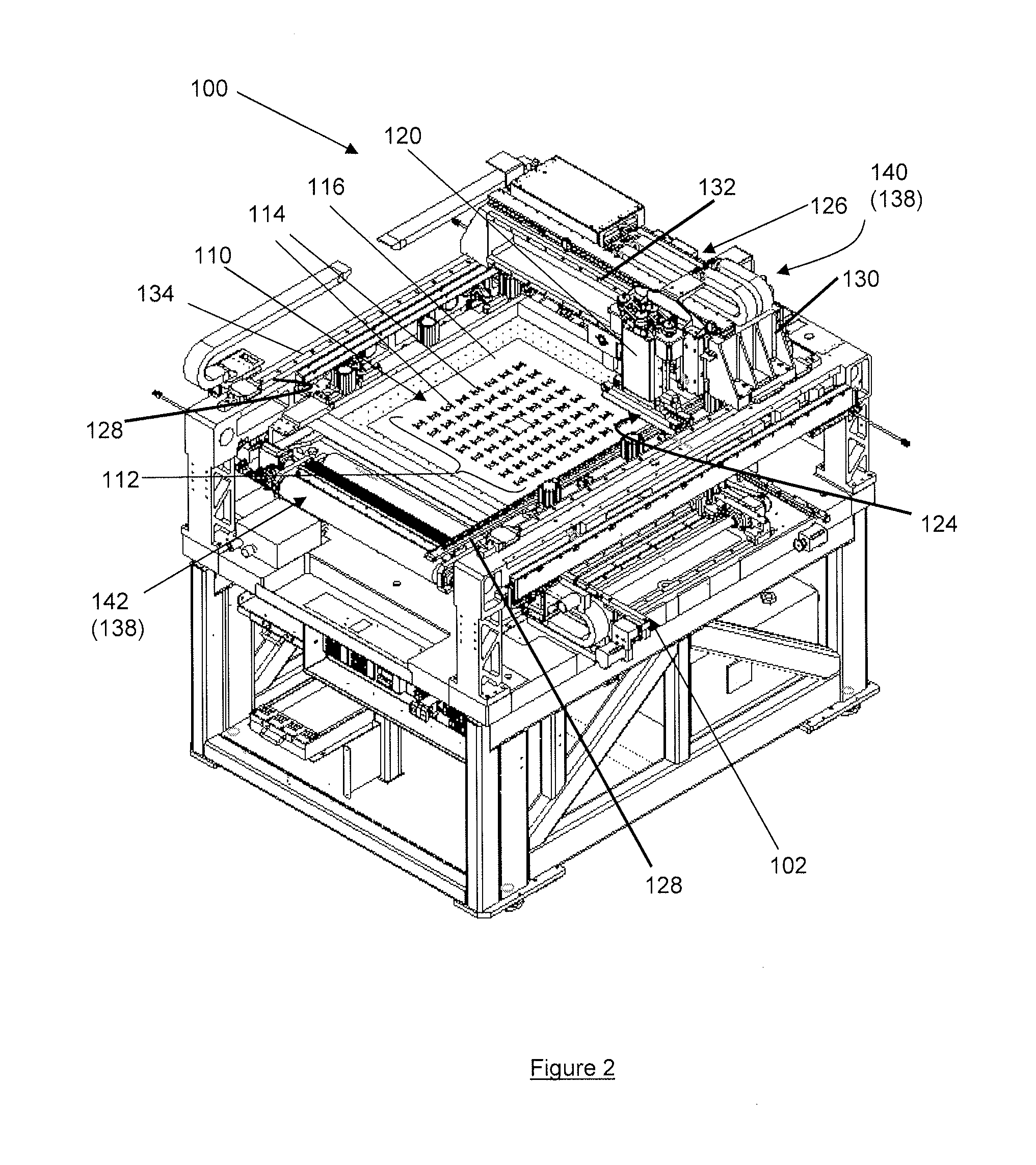
[0028]FIGS. 2 and 3 are further perspective views of the screen printer 100 in directions A and B of FIG. 1 respectively and with the pair of pivotable covers 106 and at least some of the protective panels 108 omitted to show internal parts of the screen printer 100. The screen printer 100 includes a stencil 110 having a print pattern 112 defined by a plurality of apertures 114 through which paste material is deposited onto respective solder pads of the PCB. In this embodim...


PUM


Abstract

An SMT screen printer 100 is disclosed herein. In a described embodiment, the screen printer 100 comprises: i) a stencil 110 with a plurality of apertures; ii) a paste dispenser arranged to dispense a paste material through the plurality of apertures of the stencil to form a print pattern of the stencil to form a print pattern of the paste material on an electronic device; iii) an image capturing device in the form of a fiducial camera 176 arranged to capture at least one image of the plurality of apertures 114 of the stencil 110; iv) a processor 180 arranged to select which of the apertures 114 require cleaning based on the at least one captured image; and v) a cleaning device 138 arranged to clean the selected apertures 114. A method of cleaning a stencil 110 of an SMT screen printer 100 is also disclosed

Description

BACKGROUND AND FIELD[0001]This invention relates to a screen printer (or sometimes called “stencil printer”) in the field of Surface Mount Technology (“SMT”), more particularly but not exclusively, for solder paste printing. This invention also relates to a method of cleaning a stencil (or a screen) of a screen printer.[0002]In SMT, a stencil is normally placed over an electronic device, such as a printed circuit board (PCB) having solder pads on which respective leads of a surface mount component are placed. The stencil includes apertures which correspond to respective solder pads and a solder paste printing process is used to print solder paste on the solder pads. After a few printings, the apertures of the stencil may be partially blocked by residual solder paste and the entire stencil should be cleaned to prevent bridging, mis-printings or defects. For stencils with very small apertures (for example small area-ratio apertures), the apertures may become blocked more easily and it...

Claims


Application Information

Patent Timeline
IPC IPC(8): B41F35/00
CPCB41F35/003B41F19/007B41F21/106B41F35/005B41F15/12B41P2215/00B41P2215/12B41F15/20
Inventor ONG, SEE YAPFAN, KUN QUANKWAN, KA SHING
Owner ASMPT SINGAPORE PTE LTD
Why Eureka
Try Eureka