Imaging apparatus and method of controlling same

a technology of imaging apparatus and control method, which is applied in the field of imaging apparatus, can solve the problems that the ability to check whether or not a desired image processing effect is acquired, and achieve the effect of increasing the range, and ensuring the effect of image quality

Active Publication Date: 2015-02-05
CANON KK
View PDF7 Cites 53 Cited by
  • Summary
  • Abstract
  • Description
  • Claims
  • Application Information

AI Technical Summary

Benefits of technology

[0073]With the imaging apparatus according to this embodiment, as described above, the depth map for display is acquired and synthesized at the time of shooting and displayed in the display unit. Accordingly, the photographer can easily check the current working range for shooting. Further, in the case where the photographer has instructed a change in the working range, the shooting parameter for depth map acquisition is changed automatically, so that measurement is possible in the designated working range. Accordingly, there is an effect that the photographer can acquire the depth map of the desired working range and that a desired image processing result can further be acquired reliably.
[0074]In the example above, the DFD approach is described as a depth map acquiring method. However, application is also possible in the case of the DFF approach. The DFF approach is suitable for a case where an imaging apparatus can be fixed and a subject is still. In such a case, the overall flow of processing is not changed, and a change in only the respective circuits and content of processing suffices.
[0075]First, it suffices that the depth map parameter calculation circuit 107 hold the focus bracket amount and the initial value of range for each shooting condition. It suffices that the depth map calculation circuit 106 calculate an evaluation value such as a contras value within identical local regions in a plurality of shot images and estimate the depth from the image with the highest evaluation value using expression 1 and expression 2 to calculate a depth map. The depth map created in this manner is synthesized with a viewing image and displayed in a similar manner to the case of DFD, and a photographer checks the working range. The photographer gives a change instruction for the working range if necessary. In the case of DFF, the working range is a focus bracket range itself. Therefore, it suffices to increase the range while the number of images is made constant.
[0076]In a manner described above, it is possible to check and change the working range of the depth map before shooting is complete also with DFF, and there is an effect that the photographer can reliably acquire a desired image processing result in a similar manner to the case of DFD.
[0077]Next, as a second example of the present invention, a case where a depth map is acquired with a twin-lens stereo approach and a desired image processing is performed will be described using the drawings.
[0078]The configuration of an imaging apparatus in this example is shown in FIG. 4. Those in the imaging apparatus of this example that are common with the imaging apparatus 1 shown in FIG. 1 are denoted by the same reference numerals as in FIG. 1, and only the differences will be described.

Problems solved by technology

However, since a depth map conventionally has not been checkable at the time of shooting, there has been a problem that whether or not a desired image processing effect is acquirable cannot be checked until an image processing result after shooting is observed.

Method used


Image

  • Imaging apparatus and method of controlling same
  • Imaging apparatus and method of controlling same
  • Imaging apparatus and method of controlling same

Examples


example 1

[0055]A preferred embodiment of the present invention will be described below with reference to the drawings. Note that the scope of the invention is not limited to an example illustrated in the description of the embodiments.

(Configuration)

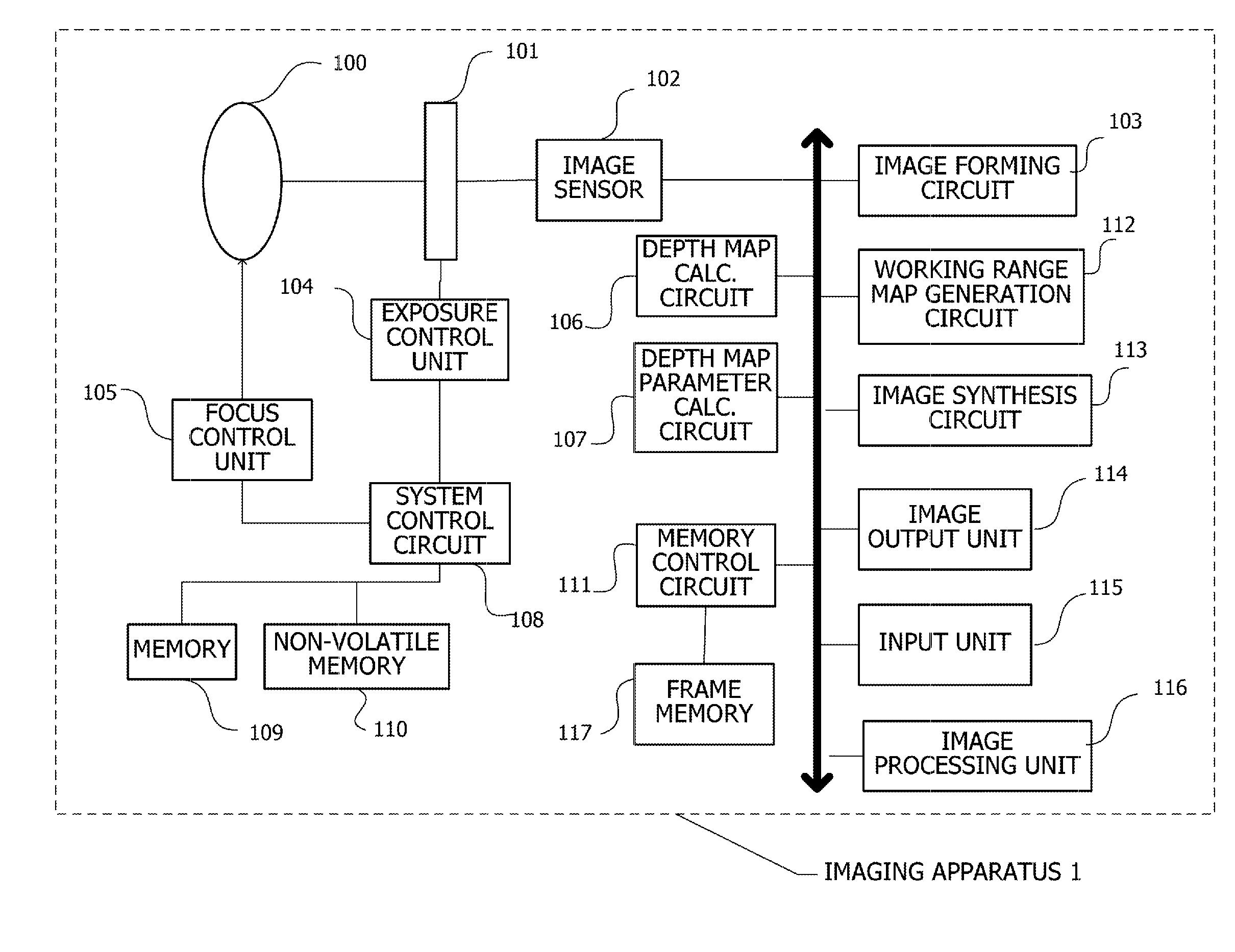
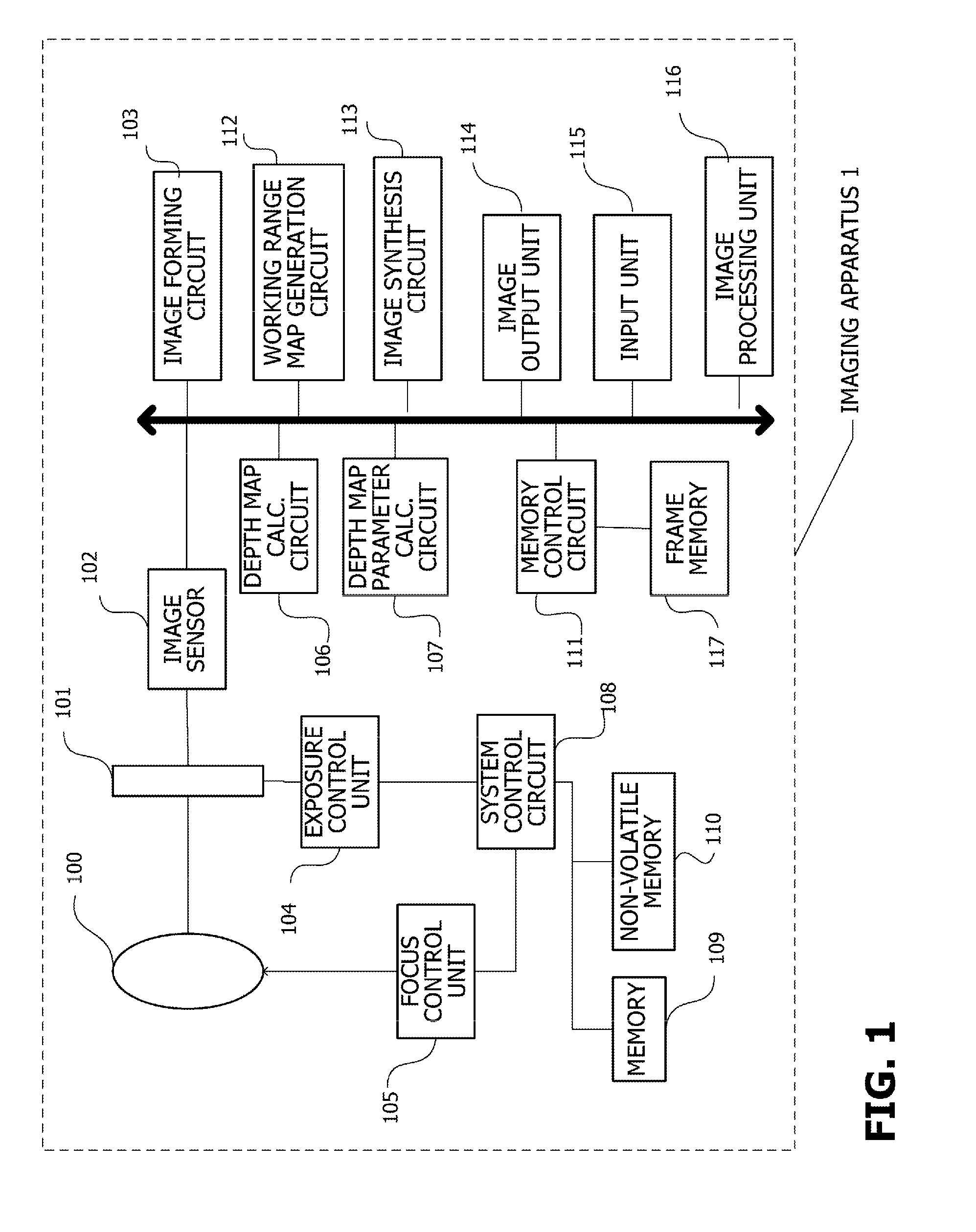
[0056]FIG. 1 schematically shows the configuration of an imaging apparatus 1 according to this embodiment. The imaging apparatus 1 acquires a depth map with the DFD method. A lens 100 guides subject light to an image sensor 102. An exposure control member 101 includes an aperture, shutter, and the like. Subject light that has entered through the lens 100 enters the image sensor 102 via the exposure control member 101. The image sensor 102 is an image sensor typically configured of an image sensor such as a CCD or CMOS, so that subject light is converted into an electrical signal and output. An image forming circuit 103 is an image forming circuit for digitalizing and imaging an analog signal output from the image sensor 102. The image forming cir...

example 2

[0077]Next, as a second example of the present invention, a case where a depth map is acquired with a twin-lens stereo approach and a desired image processing is performed will be described using the drawings.

(Configuration)

[0078]The configuration of an imaging apparatus in this example is shown in FIG. 4. Those in the imaging apparatus of this example that are common with the imaging apparatus 1 shown in FIG. 1 are denoted by the same reference numerals as in FIG. 1, and only the differences will be described.

[0079]Since an imaging apparatus 4 according to this example employs a twin-lens stereo approach, one set of a lens 500, an exposure control member 501, and an image sensor 502 are added. The exposure control unit 104 and the focus control unit 105 for control thereof control two sets of the exposure control member and the lens. The image forming circuit 503 images the output from the two image sensors 102 and 502. A depth map calculation circuit 506 and a depth map parameter ...


PUM


Abstract

An imaging apparatus comprising: an image acquisition unit configured to acquire an image; a depth map acquisition unit configured to acquire a first depth map; a working range map generation unit configured to generate a working range map showing a working range in the image on the basis of the first depth map; a synthesizing unit configured to synthesize the image and the working range map and to generate a synthesized image; and a display unit configured to display the synthesized image.

Description

BACKGROUND OF THE INVENTION[0001]1. Field of the Invention[0002]The present invention relates to an imaging apparatus and particularly relates to an imaging apparatus capable of acquiring a depth map.[0003]2. Description of the Related Art[0004]As conventional approaches to acquire a depth map simultaneously with an image for viewing, there are a stereo approach (e.g., Patent Literature 1), depth from defocus (DFD) (Patent Literature 2), depth from focus (DFF) (Patent Literature 3), and the like. These approaches are passive approaches that do not require special lighting and therefore are suitable for a general imaging apparatus. DFD and DFF are methods in which, based on blurs in shot images being different depending on the depth to a photo scene from an imaging apparatus, the difference in blur of a group of images (two or more images) shot under a plurality of shooting conditions are analyzed to calculate a depth map. The stereo method, on the other hand, is based on the princip...

Claims


Application Information

Patent Timeline
Patent Type & Authority Applications(United States)
IPC IPC(8): H04N13/02
CPCH04N13/0207H04N13/271H04N13/236
Inventor TAKAHASHI, TAKAHIROKOMATSU, SATORU
Owner CANON KK
Why Eureka
Try Eureka