Automatic tool storing mechanism

a tool and automatic technology, applied in the field of automatic tool storage mechanisms, can solve the problems of inability to move long or fast, and the claws need high rigidity to firmly grab the tools, so as to improve the overall transportation efficiency of the pots with tools from the main magazine to the sum magazin

Active Publication Date: 2015-02-05
KITAMURA MACHINERY
View PDF13 Cites 4 Cited by
  • Summary
  • Abstract
  • Description
  • Claims
  • Application Information

AI Technical Summary

Benefits of technology

[0055]The total transportation efficiency of the pots with tool

Problems solved by technology

The disadvantage of this method is that a heavy or long cutting tool is liable to lean during transportation, thereby causing i

Method used


Image

  • Automatic tool storing mechanism
  • Automatic tool storing mechanism
  • Automatic tool storing mechanism

Examples


Embodiment Construction

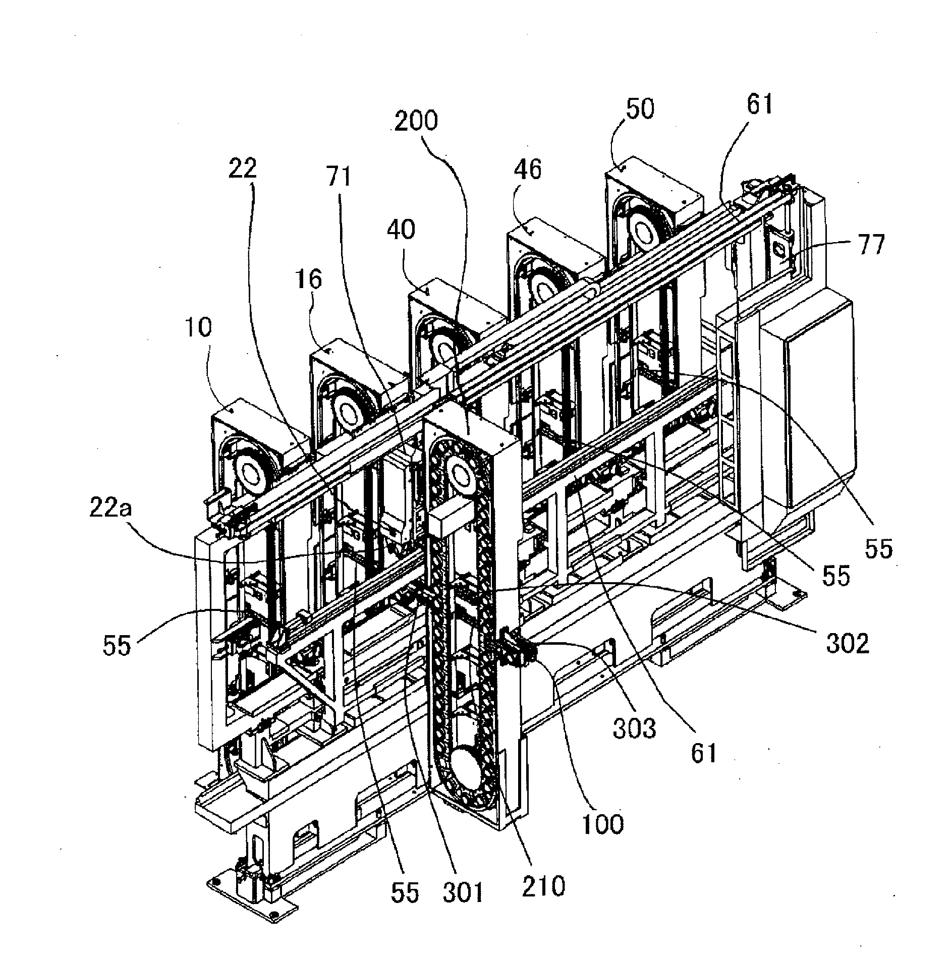
[0086]FIG. 11 is a schematic perspective view showing a main part of the automatic tool storing mechanism according to one embodiment of the present invention.

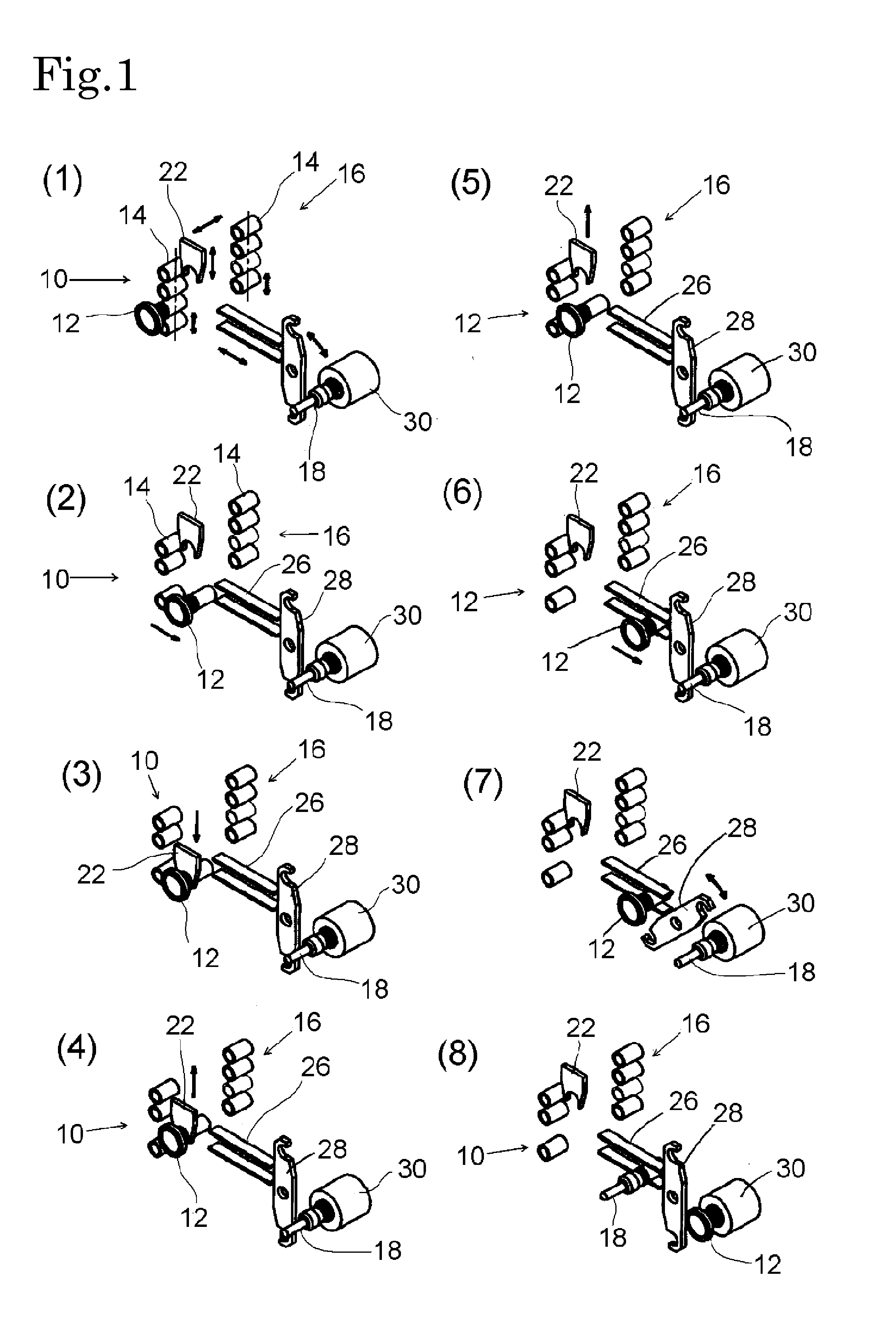
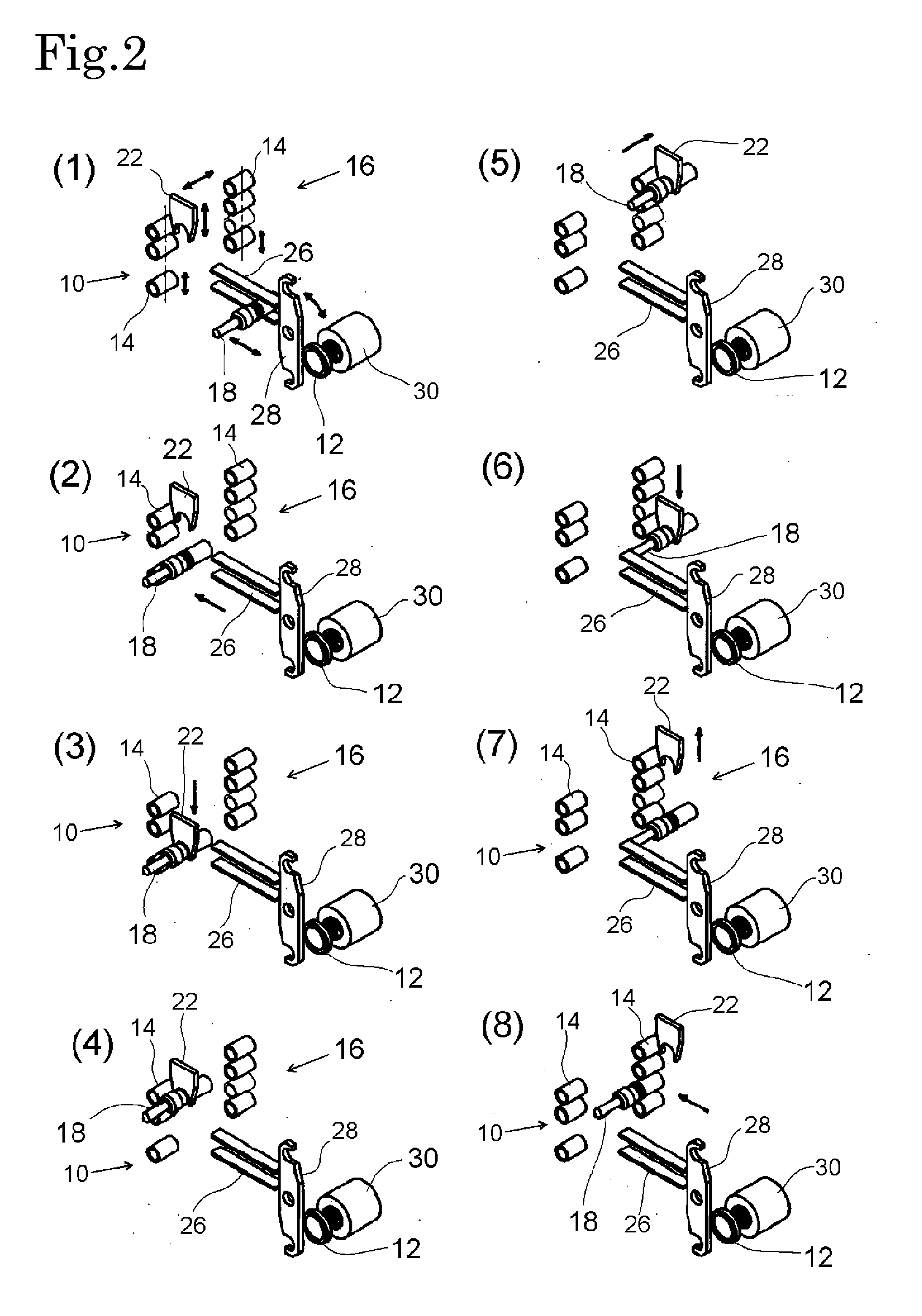
[0087]The conventional automatic tool storing mechanism shown in FIGS. 1 to 10 will be compared with the automatic tool storing mechanism shown in FIGS. 11 to 12 according to the present invention.

[0088]Five magazines 10, 16, 40, 46, 50, which are arranged in a line or one row, are called “main magazines”. Regarding the five main magazines, two guides 61, and pot moving arm 22, there are no substantial differences between the conventional automatic tool storing mechanism and the automatic tool storing mechanism according to the present invention.

[0089]In the conventional automatic tool storing mechanism, no sub magazine for the provisional storing purpose is provided.

[0090]According to the present invention, a sub magazine 200 for the provisional storing purpose is additionally provided between the waiting position 100 near or...


PUM


Abstract

An automatic tool storing mechanism has a plurality of main magazine, transporting means, and a tool exchanging arm. Each main magazine holds a large number of pots with tools. The transporting means transports the pots with tools one by one between the main magazine and the waiting position close to the main spindle. The tool exchanging arm takes out an unused or preused pot with tool which is waiting at the waiting position and attaches it to the main spindle and also removes the used tool from the main spindle and places it in the pot.

Description

BACKGROUND OF THE INVENTION[0001]1. Field of the Invention[0002]The present invention relates to an automatic tool storing mechanism equipped with a magazine to store a large number of tools and pots.[0003]2. Description of the Related Art[0004]Most machine tools, especially machining centers, are equipped with an automatic tool exchanging mechanism. They recently need a large number of tools. They are provided with many magazines to store the increased tools. Each magazine stores a large number of pots which are connected by chains. Pots are provided with a variety of tools.[0005]A conventional automatic tool exchanging device, as disclosed in Japanese Patent Laid-open Nos. 2003-291046 and 2008-155343, is composed of a magazine holding a large number of tools and pots, means for taking out a tool (held in a particular pot) from the magazine and transporting it to a waiting position, and a tool exchanging arm which exchanges the unused tool (which is waiting at the waiting position)...

Claims


Application Information

Patent Timeline
IPC IPC(8): B23Q3/155B23Q3/157
CPCB23Q3/15526B23Q3/1572B23Q3/1554B23Q3/15713B23Q3/15773B23Q3/15539B23Q2003/15532B23Q2003/155418B23Q2003/155428Y10T483/175Y10T483/1776Y10T483/1783Y10T483/1788Y10T483/1855B23Q3/15724B23Q3/15766B23Q2003/1553
Inventor KITAMURA, AKIHIROKITAMURA, KOSAKU
Owner KITAMURA MACHINERY
Why Eureka
Try Eureka